All Activity
- Today
-
Had a play took a different tack, still needs some more improvements like do a search for all existing labels and return max number do that 1st. The angle returned at a pline point determines wether the label goes below or on top that needs to be looked also. But it does use a Mid point method. needs localising of variables etc. Call it version one. ; Label pline roads ; By CivilTechForce July 2026 ; Modified by AlanH July 2026 ;;; ========================================================================= ;;; USER CONFIGURATION - EDIT THESE VARIABLES EASILY ;;; ========================================================================= ;;; Check does layer exist (defun chklay (layn color ltype / ) (command "-layer" "make" layn "C" color "" "LT" ltype "" "") ) (defun alg-ang (obj pnt) (angle '(0. 0. 0.) (vlax-curve-getfirstderiv obj (vlax-curve-getparamatpoint obj pnt ) ) ) ) ;;; MTEXT CREATION FUNCTION (WITH ROTATION & READABILITY LOGIC) (defun action-label-road (road-entity number / ang readable-ang) (setq ang (alg-ang obj mid-param)) (if (and (> ang (/ pi 2.0)) (<= ang (* pi 1.5))) (setq readable-ang (+ ang pi)) ; Flip 180 degrees if necessary (setq readable-ang ang) ; Keep original angle otherwise ) (setq mid-param (polar mid-param (- (/ pi 2.0) ang) road-text-height)) (entmake (list (cons 0 "MTEXT") (cons 100 "AcDbEntity") (cons 8 road-text-layer) ; Applies your layer (cons 62 road-text-color) ; Applies your color (cons 100 "AcDbMText") (cons 10 mid-param) ; Places text at the middle of the road (cons 40 road-text-height) ; Applies your text size (cons 50 readable-ang) ; <--- APPLIES CALCULATED READABLE ROTATION (cons 71 5) ; Forces "Middle Center" alignment (cons 1 (strcat global:road-prefix " " (itoa number))) ; Text content ) ) (setq global:road-counter (1+ global:road-counter)) (princ) ) ;;; ========================================================================= (vl-load-com) ; Loads advanced geometry functions for handling polylines (defun c:NumberRoads ( / road-ss user-prefix road-text-layer road-text-color road-default-prefix) (setq road-text-height 2.5) ; How tall the road number text should be (chklay "Road-Labels" 1 "Continuous") ; Does layer exist check (setq road-text-layer "Road-Labels") ; The layer where the text numbers will go (setq road-text-color 2) ; Color index for the text numbers (2 = Yellow) (setq road-default-prefix "Road") ; The default name if you just press Enter (setq error-circle-radius 5.0) ; How big the warning circles should be (setq error-circle-layer "Unnamed-Roads") ; Layer for roads that were skipped (setq error-circle-color 1) ; Color for warning circles (1 = Red) (princ "\nSelect all polylines and lines that make up the road network: ") (setq road-ss (ssget '((0 . "LINE,*POLYLINE")))) (if road-ss (progn (setq global:road-counter (getint "\nEnter new Road profile number eg 1 ")) (setq user-prefix (getstring t (strcat "\nEnter road prefix <" road-default-prefix ">: "))) (if (= user-prefix "") (setq global:road-prefix road-default-prefix) (setq global:road-prefix user-prefix) ) (setq x 0) (while (< x (sslength road-ss)) (setq road-entity (ssname road-ss x)) (setq obj (vlax-ename->vla-object road-entity)) (setq dist (/ (vlax-get obj 'length) 2.0)) (setq mid-param (vlax-curve-getpointatdist obj dist)) (setq lst2 '() angstep 0.785398163397448 ang2 0.0) (repeat 8 (setq lst2 (cons (polar mid-param ang2 road-text-height) lst2)) (setq lst2 (cons (last lst2) lst2)) (setq ang2 (+ ang2 angstep)) ) (setq ss2 (ssget "F" lst2 (list (cons 0 "Mtext")(cons 8 road-text-layer)))) (if ss2 (princ "\npline already labelled") (action-label-road road-entity global:road-counter) ) (setq x (1+ X)) ) ) ; progn ss (princ) ) ; if ss (princ) ) I am leaning towards making the input here much bigger rather than lots of setq's just set default values in the defun call. Or use a dcl to set values. (defun action-label-road (road-entity number / mid-param mid-pt deriv ang readable-ang) (defun action-label-road (road-entity number road-text-layer road-text-color global:road-prefix) / mid-param mid-pt deriv ang readable-ang)
-

Beyond APPLOAD: A local script manager for those of us with too many LISPs
VicoWang replied to VicoWang's topic in AutoLISP, Visual LISP & DCL
Hi BIGAL, First off, thank you for sharing your perspective on how the community and your clients are handling the "cloud" today. It’s really insightful to hear where the landscape actually stands from someone with your experience. You’re spot-on that most people currently just map AutoCAD Support Paths to a static cloud drive folder. And that "In office" / "Out of office" dual-icon setup you mentioned? That is a brilliant piece of classic IT problem-solving! It perfectly captures the exact nightmare CAD Managers have dealt with for years when engineers take laptops to construction sites. Analyzing those classic IT workarounds highlights that the core deployment challenges in CAD haven't changed, but modern architectures give us new ways to tackle them. At their core, almost all traditional methods—whether passing local ZIPs or mapping static cloud drives—rely on static distribution. Once a file leaves the source, its connection is severed, inevitably leading to version fragmentation across the firm. This is exactly why we designed VedaCAD to provide dynamic lifecycle management through a "Cloud-Managed Local Sandbox", rather than just live cloud mapping. From an engineering standpoint, here is how we structured the technical measures to handle those specific scenarios: Solving the offline field scenario Mapping directly to a cloud drive introduces fragility—if the internet drops, CAD freezes. To prevent this, everything in our architecture physically runs from a local sandbox cache on the C drive. The client simply pings the server with a lightweight heartbeat. If an engineer opens their laptop on a site with zero Wi-Fi, the LISP kernel silently transitions into Offline Mode. They keep drawing seamlessly using their local cache until the configured offline grace period expires. No need for separate desktop icons. Managing binary updates and file locks When a developer patches a .vlx or .dll, expecting users to manually download and replace ZIPs leads to version fragmentation. We shifted this to a heartbeat-driven sync. When the server detects a version drift, the update is pulled into the sandbox. Depending on the workspace policy (Manual, Auto, or Enforced), the user either clicks to approve it, or the engine hot-swaps it silently in the background. To bypass Windows file locks on running binaries, the engine utilizes a backend .bak renaming trick to perform the in-place replacement without crashing CAD. Resolving subcontractor environment consistency How do we ensure that all subcontractors perfectly align with the drafting standards set by the general contractor, even down to the absolute uniformity of a single linetype color? We tackled this by building isolated containment fields we call "Project Arks". Instead of emailing ZIP files of CAD standards, a General Contractor can package their absolute drafting environment and issue a time-limited "Visa". When a subcontractor mounts it, their CAD temporarily mirrors the GC's standard. Crucially, if the GC updates a .ctb or other environment configuration files mid-project, the subcontractors pull the latest standard on their next heartbeat or upon manual sync, allowing the GC to monitor exactly which external terminals are lagging on outdated standards. Asset revocation and self-healing If a subcontractor's Visa expires, or an internal employee's device is unbound, the system relies on a zero-trust model. Upon the next ping, the engine executes a remote kill-switch, physically shredding the proprietary CAD assets from the local cache. Conversely, if a user accidentally deletes a cached plugin, the LISP reactor detects the loss via a native (findfile) check and instantly auto-fetches the replica from the cloud, ensuring the execution chain never breaks. It’s always a pleasure geeking out over deployment architectures with veterans. Thanks again for the great discussion! Cheers, Vico -
 hakimumay joined the community
 -
Did not look to hard but an obvious one for me was. (setq road-text-layer "Road-Labels") ; The layer where the text numbers will go If layer "Road=labels" does not exist then program will crash, IF does not exist so just "Make" the layer. In lots of code I am writing I will take advantage of a global defun that is in another preloaded lisp, it has a checklayer function. This something like all you would need. (chklayer "Road-Label" 1 "Continous") (setq road-text-layer "Road-Labels") Agree with other post label at mid point, Using vertices can get be returned form a pline that is drawn in wrong direction than you think. Yours (setq current-dist-start (vlax-curve-getDistAtPoint road-entity start-pt)) I have a swap or flip a pline so start direction is from end selected. But using mid solves this. May not need this function if using mid. There is VL get coordinates that returns all the vertice XYZ. (defun helper-find-and-sort-intersections (setq lst (vlax-safearray->list (vlax-variant-value (vla-get-coordinates obj)))) Also this for pline vertice points, thanks to lee--mac. (setq plent (entsel "\nPick rectang")) (if plent (setq co-ord (mapcar 'cdr (vl-remove-if-not '(lambda (x) (= (car x) 10)) (entget (car plent)))))) (princ co-ord) Just another idea when doing add more items to an existing drawing, do a "does the labels exist already" ? If so then get them all and find last label then add one to it. You have a layer name so can ssget MTEXT for that layer. Just me I don't tend to do this, make a list of entities, then process that list. It's a personal preference (while (setq entity (ssname road-ss i)) (setq global:all-roads (cons entity global:all-roads)) (setq i (1+ i)) ) I just act on the current entity returned by the while or a Repeat and do the labelling of that entity. This is sort of double handling the SSGET if you use Pick PIck Pick method the selection set should be in the pick order (setq first-road (car (entsel "\nSelect the FIRST road (from your selection): "))) Otherwise use a Pick and label method it will be fast. The label will appear as fast as you pick. Maybe even a dual method pick and window. Having a bit of a look I think code can be shortened a lot.
-

Beyond APPLOAD: A local script manager for those of us with too many LISPs
BIGAL replied to VicoWang's topic in AutoLISP, Visual LISP & DCL
@VicoWang I don't do anything with the clous but I know some of my clients are going that way for various reasons, in the very simple way the Install.lsp works there is no reason why the programs etc can not be loaded to the cloud. You only need correct support paths hopefully set, I don't use the cloud. One other thing is we had laptops where I worked, so when outside in the field the user would select the correct icon on the desktop, we had two icons "In office" and "Out of office" then the correct profile was loaded. The "out of office" would look on the laptop for programs etc, Yes had a slightly different set of menu's. The profile choice is in the ICON properties. - Yesterday
-
Hello. May I make a suggestion? Perhaps you could simplify the user prompts from this: (setq first-road (car (entsel "\nSelect the FIRST road (from your selection): "))) (setq start-point (getpoint "\nClick near the START point of the first road: ")) to a single prompt: (setq first-road (car (setq es (entsel "\nSelect the FIRST road near the START point (from your selection): "))) start-point (cadr es) ) Also, your code calculates the midpoint based on the number of vertices rather than on the actual distance along the road. You might prefer to place the label at the geometric midpoint by replacing this: (setq mid-param (/ (vlax-curve-getEndParam road-entity) 2.0)) with this: (setq total-dist (vlax-curve-getDistAtParam road-entity (vlax-curve-getEndParam road-entity)) mid-param (vlax-curve-getParamAtDist road-entity (/ total-dist 2.0)) )
-

Beyond APPLOAD: A local script manager for those of us with too many LISPs
Nikon replied to VicoWang's topic in AutoLISP, Visual LISP & DCL
Type VC to start. Read it on the command line when loading .VLX. -

Beyond APPLOAD: A local script manager for those of us with too many LISPs
lucas0510_12311 replied to VicoWang's topic in AutoLISP, Visual LISP & DCL
i got .vlx file and i dont know the command pls -
 omer ozcan joined the community
 - Last week
-
Watching this whole "AI taking over" debate unfold, I feel like I'm seeing people in our industry fall into three different camps: First, there’s the Spectator. They use AI to generate flashy concept art or write basic emails. It’s pure consumption—cool to look at, but they don't really know how the engine works. Then you have the Skeptical Co-Pilot. This is where I sit for my daily development. You let AI do the heavy lifting for specific, tedious tasks, but you absolutely do not trust it blindly. You sandbox its output and rigorously test it before ever putting it into your actual workflow. Finally, there’s the Blind Believer. This is the whole "AI Agent" crowd trying to run a one-man firm. They type a prompt and expect a flawless final product the next morning. The reality? You have no idea what kind of spaghetti code or geometric garbage is hidden inside that black box, and auditing it takes longer than just doing the work yourself. Speaking of that "skeptical co-pilot" approach, I actually went down a massive rabbit hole with it recently. I was trying to solve a very pragmatic problem: How do we get an LLM to generate hyper-precise CAD geometry without eating up a million tokens and spitting out hallucinated garbage? Natural language just doesn't cut it for drafting. So, I worked with an AI to invent a prototype "Universal Morphological Matrix" (I just call it V-Code). The idea was to strip away all the human linguistic fluff and reduce CAD commands down to an absolute, 256-token hex-based root system. It basically compresses professional CAD knowledge into a tiny "Cosmic Language", which a local interpreter can then unpack back into precise AutoCAD/LISP commands. I pushed the experiment so far that I jokingly asked the AI to use this highly compressed logic to solve the P vs NP math problem. It confidently spit out a bunch of hex codes and claimed it had solved it. Did I believe it? Absolutely not, because I couldn't read its alien derivation track at all, haha! At the end of the day, AI is an incredibly powerful engine. But if you take your hands off the steering wheel and just blindly trust the machine, you're going to crash. It remains a tool exclusively for people who already know exactly what they are doing.

-
Hi, With help of AI I manage to get this lisp working. Name my Roads. Allows the user to select number of polylines and then select starting polyline (Road) and names all the rest. I would welcome any further improvements on it. ;;; ========================================================================= ;;; USER CONFIGURATION - EDIT THESE VARIABLES EASILY ;;; ========================================================================= (setq road-text-height 2.5) ; How tall the road number text should be (setq road-text-layer "Road-Labels") ; The layer where the text numbers will go (setq road-text-color 2) ; Color index for the text numbers (2 = Yellow) (setq road-default-prefix "Road") ; The default name if you just press Enter (setq error-circle-radius 5.0) ; How big the warning circles should be (setq error-circle-layer "Unnamed-Roads") ; Layer for roads that were skipped (setq error-circle-color 1) ; Color for warning circles (1 = Red) ;;; ========================================================================= (vl-load-com) ; Loads advanced geometry functions for handling polylines (defun c:NumberRoads ( / road-ss user-prefix first-road start-point i entity) ;; Reset our trackers (setq global:road-counter 1) (setq global:all-roads '()) (setq global:visited-list '()) (princ "\nSelect all polylines and lines that make up the road network: ") (setq road-ss (ssget '((0 . "LINE,*POLYLINE")))) (if road-ss (progn ;; Convert the selection set into a clean list of entities for the algorithm (setq i 0) (while (setq entity (ssname road-ss i)) (setq global:all-roads (cons entity global:all-roads)) (setq i (1+ i)) ) (setq user-prefix (getstring t (strcat "\nEnter road prefix <" road-default-prefix ">: "))) (if (= user-prefix "") (setq global:road-prefix road-default-prefix) (setq global:road-prefix user-prefix) ) (setq first-road (car (entsel "\nSelect the FIRST road (from your selection): "))) (setq start-point (getpoint "\nClick near the START point of the first road: ")) (if (and first-road start-point) (progn ;; Start the main driving loop (explore-road-logic first-road start-point) ;; SCAN FOR UNNAMED ROADS: Look for any lines left behind (foreach entity global:all-roads (if (not (member entity global:visited-list)) (action-mark-unnamed entity) ) ) (princ "\nRoad numbering complete! Skipped roads have been marked with red circles.") ) (princ "\nMissing first road or start point selection.") ) ) (princ "\nNo roads were selected.") ) (princ) ) ;;; CORE LOGIC FUNCTION (defun explore-road-logic (current-road current-start-pt / road-num intersections intersection-info next-road next-pt) (setq road-num global:road-counter) (setq global:visited-list (cons current-road global:visited-list)) (action-label-road current-road road-num) (setq intersections (helper-find-and-sort-intersections current-road current-start-pt)) (foreach intersection-info intersections (setq next-pt (car intersection-info)) (setq next-road (cdr intersection-info)) (if (not (member next-road global:visited-list)) (progn (setq global:road-counter (+ global:road-counter 1)) (explore-road-logic next-road next-pt) ) ) ) ) ;;; MTEXT CREATION FUNCTION (WITH ROTATION & READABILITY LOGIC) (defun action-label-road (road-entity number / mid-param mid-pt deriv ang readable-ang) (setq mid-param (/ (vlax-curve-getEndParam road-entity) 2.0)) (setq mid-pt (vlax-curve-getPointAtParam road-entity mid-param)) (setq deriv (vlax-curve-getFirstDeriv road-entity mid-param)) (setq ang (angle '(0 0 0) deriv)) ; Convert vector to angle in radians (if (and (> ang (/ pi 2.0)) (<= ang (* pi 1.5))) (setq readable-ang (+ ang pi)) ; Flip 180 degrees if necessary (setq readable-ang ang) ; Keep original angle otherwise ) (entmake (list '(0 . "MTEXT") '(100 . "AcDbEntity") (cons 8 road-text-layer) ; Applies your layer (cons 62 road-text-color) ; Applies your color '(100 . "AcDbMText") (cons 10 mid-pt) ; Places text at the middle of the road (cons 40 road-text-height) ; Applies your text size (cons 50 readable-ang) ; <--- APPLIES CALCULATED READABLE ROTATION '(71 . 5) ; Forces "Middle Center" alignment (cons 1 (strcat global:road-prefix " " (itoa number))) ; Text content )) ) (defun action-mark-unnamed (road-entity / mid-param mid-pt) (setq mid-param (/ (vlax-curve-getEndParam road-entity) 2.0)) (setq mid-pt (vlax-curve-getPointAtParam road-entity mid-param)) (entmake (list '(0 . "CIRCLE") '(100 . "AcDbEntity") (cons 8 error-circle-layer) (cons 62 error-circle-color) '(100 . "AcDbCircle") (cons 10 mid-pt) (cons 40 error-circle-radius) )) ) (defun helper-find-and-sort-intersections (road-entity start-pt / road-vla intersections-list current-dist-start other-vla int-points pt dist rel-dist abs-rel-dist) (setq road-vla (vlax-ename->vla-object road-entity)) (setq current-dist-start (vlax-curve-getDistAtPoint road-entity start-pt)) (if (not current-dist-start) (setq current-dist-start 0.0)) (setq intersections-list '()) (foreach other-entity global:all-roads (if (and (not (eq road-entity other-entity)) (not (member other-entity global:visited-list))) (progn (setq other-vla (vlax-ename->vla-object other-entity)) (setq int-points (vlax-invoke road-vla 'IntersectWith other-vla 0)) (if int-points (while int-points (setq pt (list (car int-points) (cadr int-points) (caddr int-points))) (setq int-points (cdddr int-points)) (if (vlax-curve-getDistAtPoint road-entity pt) (progn (setq dist (vlax-curve-getDistAtPoint road-entity pt)) (setq abs-rel-dist (abs (- dist current-dist-start))) (if (> abs-rel-dist 0.01) (setq intersections-list (cons (list abs-rel-dist pt other-entity) intersections-list)) ) ) ) ) ) ) ) ) (setq intersections-list (vl-sort intersections-list '(lambda (a b) (< (car a) (car b))))) (mapcar '(lambda (x) (cons (cadr x) (caddr x))) intersections-list) )
-

Introducing Block Generate with AI: An AI Tech Preview for AutoCAD on the web
The AutoCAD Blog posted a topic in AutoCAD Blogs
What if creating a CAD block was as simple as describing it, letting you spend less of your time drafting and more time designing? My team at Autodesk is exploring how AI can simplify some of your core CAD workflows. Starting today, you can get an inside look into the future of the AutoCAD portfolio through our new Tech Previews on AutoCAD on the web. We have lots more ideas in the works, and we can’t wait for you to try them! Our first Tech Preview is Block Generate with AI. You can use natural language to generate a 2D block. In the description, you can specify the shape. Some examples: 3-seater sofa with 3 cushions Double vanity with round bowls and rounded corners Round table with four chairs Double door with equal leaves and 90-degree swing arcs Designed to help you get to design faster Blocks are a fundamental part of many AutoCAD workflows, but creating a new one can interrupt your momentum. Block Generate with AI is designed to help you quickly generate a starting point so you can spend less time creating common objects and more time designing. Because the generated block is editable, you remain in control. You can modify the geometry to meet your project’s needs before incorporating it into your drawings. As a Tech Preview, generated geometry may need some editing, particularly dimensions, as we continue developing the experience. Your feedback will help us improve future iterations. Try it and tell us what you think Block Generate with AI is available as a Tech Preview in AutoCAD on the web. If you’d like to learn how to enable the Tech Preview, write effective prompts, and start generating blocks, check out our Block Generate with AI Help article. Which block will you generate first? We’d love to hear your ideas in the Autodesk Community. The post Introducing Block Generate with AI: An AI Tech Preview for AutoCAD on the web appeared first on AutoCAD Blog. View the full article -

Free Multi Plot Lisp – Fast Batch Printing for AutoCAD, BricsCAD & ZWCAD | Model/Layout, Zone Plotting & PDF Merge
CamDuy replied to CamDuy's topic in AutoLISP, Visual LISP & DCL
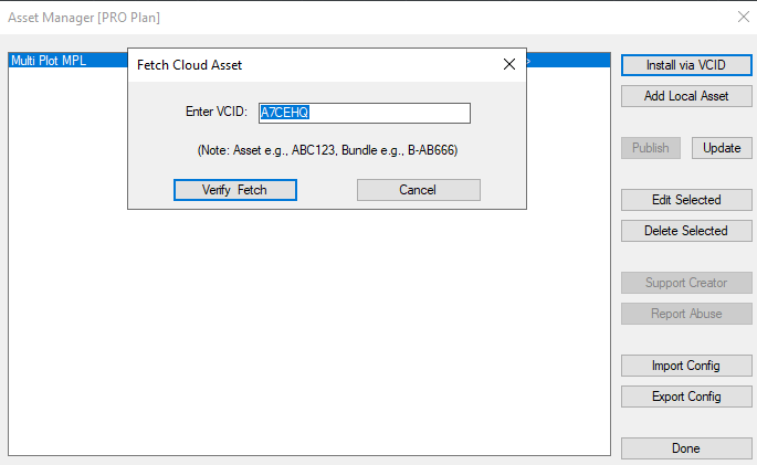
download: https://www.vedacad.com/ type code: A7CEHQ Drawing test MPL: https://drive.google.com/file/d/1WgMLRDxaiLchbshI3o_f3WHrV7rHX03e/view?usp=sharing AutoCAD: https://shrinkme.click/Multi_Plot_MPL BricsCAD: https://shrinkme.click/Multi_Plot_MPL_BricsCAD ZwCAD: https://shrinkme.click/Multi_Plot_MPL_ZwCAD
-

North direction in AutoCAD drawing does not match my real-world compass direction
tombu replied to CHICHA's topic in AutoCAD General
Generally users of AutoCAD Map and it's verticals use DVIEW (Command) Twist option to change the orientation of viewports if the software didn't automatically twist it when the sheet was created to either better show the work area or with Plan & Profile sheets the Plan view's baseline is orientated horizontal to align with the Profile view. North is rarely exactly straight up on a viewport! There should always be a North arrow and a graphic scale on every map. If not plotted at 1:1 the graphic scale will not measure correctly. Not sure what you mean by "north arrow was not very clear"? Never used an "online compass" but always viewed project areas with Google Maps or GIS software to check orientation and make sure there wasn't anything missing on my drawing. -
 Welcome to CadTutor CamDuy and thank you for sharing your program, looks like you put a lot of effort in this. The world (and this site) needs more people like you
 -

Extracting Face and Edge Information from a 3D Solid Without Exploding It
Danielm103 replied to p7q's topic in AutoLISP, Visual LISP & DCL
here's a dump from the BRep sample I posted here brep.txt -

Extracting Face and Edge Information from a 3D Solid Without Exploding It
p7q replied to p7q's topic in AutoLISP, Visual LISP & DCL
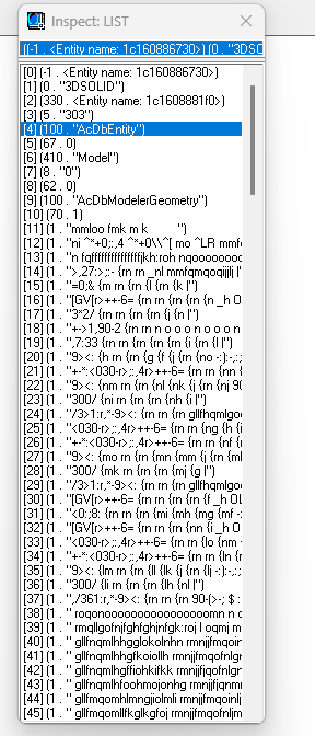
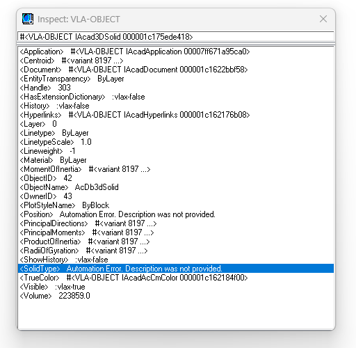
3D Solid.dwg I’ve attached a sample DWG. When I run: (setq SOLID (ssget '((0 . "3DSOLID")))) (setq data (entget (ssname SOLID 0))) I get this result: When I run: (setq data (vlax-ename->vla-object (ssname SOLID 0))) I get this result instead:
-
output for a cylinder Command: DOIT3 Select Solid: --- Face #1 | Type: kCylinder | Area: 428514.2140 --- Arc: (440.88076870446724,537.54943936113841,0.00000000000000) 198.3154183465131 Arc: (440.88076870446724,537.54943936113841,343.89739291260162) 198.3154183465131 --- Face #2 | Type: kPlane | Area: 123555.7137 --- Arc: (440.88076870446724,537.54943936113841,0.00000000000000) 198.3154183465131 --- Face #3 | Type: kPlane | Area: 123555.7137 --- Arc: (440.88076870446724,537.54943936113841,343.89739291260162) 198.3154183465131
-
from pyrx import Ap, Ax, Db, Ed, Ge, Br # iter faces @Ap.Command() def doit1(): ps, id, _ = Ed.Editor.entSel("\nPick it: ", Db.Solid3d.desc()) if ps != Ed.PromptStatus.eOk: raise RuntimeError("oof {}:".format(ps)) dbs = Db.Solid3d(id) brs = Br.Brep(dbs) ft = Br.FaceTraverser(brs) for face in ft.getFaces(): print(face.getArea()) # iter edges @Ap.Command() def doit2() -> None: ps, id, pnt = Ed.Editor.entSel("\nSelect: ", Db.Solid3d.desc()) if ps != Ed.PromptStatus.eOk: raise RuntimeError("oof {}:".format(ps)) dbent = Db.Entity(id) brep = Br.Brep(dbent) et = Br.EdgeTraverser() et.setBrep(brep) while not et.done(): edge = et.getEdge() curveType = edge.getCurveType() excurve = Ge.ExternalCurve3d.cast(edge.getCurve()) if curveType == Ge.EntityId.kLineSeg3d: seg = Ge.LineSeg3d.cast(excurve.getNativeCurve()) print(seg.length(), seg.startPoint(), seg.endPoint()) elif curveType == Ge.EntityId.kCircArc3d: carc = Ge.CircArc3d.cast(excurve.getNativeCurve()) print(carc.center(), carc.radius()) et.next() # iter faces and edges @Ap.Command() def doit3() -> None: # 1. Prompt user to select a 3D solid ps, id, pnt = Ed.Editor.entSel("\nSelect Solid: ", Db.Solid3d.desc()) if ps != Ed.PromptStatus.eOk: raise RuntimeError("Selection failed: {}".format(ps)) # 2. Get the Solid entity and open its Boundary Representation (B-rep) dbs = Db.Solid3d(id) brs = Br.Brep(dbs) # 3. Step 1: Traverse the solid's Faces ft = Br.FaceTraverser(brs) face_index = 1 for face in ft.getFaces(): # --- NEW FACE METRIC EXTRACTION --- try: face_area = face.getArea() surf_type = face.getSurfaceType() # E.g., kPlane, kCylinder, etc. print(f"\n--- Face #{face_index} | Type: {surf_type} | Area: {face_area:.4f} ---") except Exception as e: print(f"\n--- Face #{face_index} (Failed to fetch area metrics: {e}) ---") face_index += 1 # ---------------------------------- # 4. Step 2: Step down from Face to its Loops flt = Br.FaceLoopTraverser() flt.setFace(face) while not flt.done(): loop = flt.getLoop() # 5. Step 3: Step down from Loop to its Edges (using LoopEdgeTraverser) let = Br.LoopEdgeTraverser() let.setLoop(loop) while not let.done(): edge = let.getEdge() # 6. Extract and evaluate the Edge geometry curveType = edge.getCurveType() excurve = Ge.ExternalCurve3d.cast(edge.getCurve()) if curveType == Ge.EntityId.kLineSeg3d: seg = Ge.LineSeg3d.cast(excurve.getNativeCurve()) print(" Line:", seg.length(), seg.startPoint(), seg.endPoint()) elif curveType == Ge.EntityId.kCircArc3d: carc = Ge.CircArc3d.cast(excurve.getNativeCurve()) print(" Arc:", carc.center(), carc.radius()) # Move to next Edge inside this loop let.next() # Move to next Loop inside this face flt.next() output for a 3d box Command: DOIT3 Select Solid: --- Face #1 | Type: kPlane | Area: 6095.4620 --- Line: 60.13854242043337 (103.70522552029884,68.98463275333243,46.66742774827728) (103.70522552029884,8.84609033289907,46.66742774827728) Line: 101.35699658327584 (2.34822893702299,68.98463275333243,46.66742774827728) (103.70522552029884,68.98463275333243,46.66742774827728) Line: 60.13854242043337 (2.34822893702299,8.84609033289907,46.66742774827728) (2.34822893702299,68.98463275333243,46.66742774827728) Line: 101.35699658327584 (103.70522552029884,8.84609033289907,46.66742774827728) (2.34822893702299,8.84609033289907,46.66742774827728) --- Face #2 | Type: kPlane | Area: 6095.4620 --- Line: 60.13854242043337 (103.70522552029884,8.84609033289907,0.00000000000000) (103.70522552029884,68.98463275333243,0.00000000000000) Line: 101.35699658327584 (2.34822893702299,8.84609033289907,0.00000000000000) (103.70522552029884,8.84609033289907,0.00000000000000) Line: 60.13854242043337 (2.34822893702299,68.98463275333243,0.00000000000000) (2.34822893702299,8.84609033289907,0.00000000000000) Line: 101.35699658327584 (103.70522552029884,68.98463275333243,0.00000000000000) (2.34822893702299,68.98463275333243,0.00000000000000) --- Face #3 | Type: kPlane | Area: 4730.0703 --- Line: 46.66742774827728 (2.34822893702299,68.98463275333243,46.66742774827728) (2.34822893702299,68.98463275333243,0.00000000000000) Line: 101.35699658327584 (2.34822893702299,68.98463275333243,46.66742774827728) (103.70522552029884,68.98463275333243,46.66742774827728) Line: 46.66742774827728 (103.70522552029884,68.98463275333243,46.66742774827728) (103.70522552029884,68.98463275333243,0.00000000000000) Line: 101.35699658327584 (103.70522552029884,68.98463275333243,0.00000000000000) (2.34822893702299,68.98463275333243,0.00000000000000) --- Face #4 | Type: kPlane | Area: 2806.5111 --- Line: 46.66742774827728 (2.34822893702299,8.84609033289907,46.66742774827728) (2.34822893702299,8.84609033289907,0.00000000000000) Line: 60.13854242043337 (2.34822893702299,8.84609033289907,46.66742774827728) (2.34822893702299,68.98463275333243,46.66742774827728) Line: 46.66742774827728 (2.34822893702299,68.98463275333243,46.66742774827728) (2.34822893702299,68.98463275333243,0.00000000000000) Line: 60.13854242043337 (2.34822893702299,68.98463275333243,0.00000000000000) (2.34822893702299,8.84609033289907,0.00000000000000) --- Face #5 | Type: kPlane | Area: 4730.0703 --- Line: 46.66742774827728 (103.70522552029884,8.84609033289907,46.66742774827728) (103.70522552029884,8.84609033289907,0.00000000000000) Line: 101.35699658327584 (103.70522552029884,8.84609033289907,46.66742774827728) (2.34822893702299,8.84609033289907,46.66742774827728) Line: 46.66742774827728 (2.34822893702299,8.84609033289907,46.66742774827728) (2.34822893702299,8.84609033289907,0.00000000000000) Line: 101.35699658327584 (2.34822893702299,8.84609033289907,0.00000000000000) (103.70522552029884,8.84609033289907,0.00000000000000) --- Face #6 | Type: kPlane | Area: 2806.5111 --- Line: 46.66742774827728 (103.70522552029884,68.98463275333243,46.66742774827728) (103.70522552029884,68.98463275333243,0.00000000000000) Line: 60.13854242043337 (103.70522552029884,68.98463275333243,46.66742774827728) (103.70522552029884,8.84609033289907,46.66742774827728) Line: 46.66742774827728 (103.70522552029884,8.84609033289907,46.66742774827728) (103.70522552029884,8.84609033289907,0.00000000000000) Line: 60.13854242043337 (103.70522552029884,8.84609033289907,0.00000000000000) (103.70522552029884,68.98463275333243,0.00000000000000)
-
So I received an email this morning and this is the caption that described one of the articles (I haven't read it yet)...
-

Extracting Face and Edge Information from a 3D Solid Without Exploding It
SLW210 replied to p7q's topic in AutoLISP, Visual LISP & DCL
Can you post a sample drawing of what you would mostly be working with? I am sure Daniel would be better than me at this, though. -
 Kalyan 070402 joined the community
 -

North direction in AutoCAD drawing does not match my real-world compass direction
eldon replied to CHICHA's topic in AutoCAD General
No. In days, long ago, before GPS and AutoCAD, surveys were plotted on paper, and the indication of North was not compulsory. I suspect that the old ways are gradually fading in the light of new technology, but not all surveys, even nowadays, are measured with GPS assistance. In the past I have used the national mapping to check North alignment, but that is usually on the grid projection that is being used. As most survey mapping is drawn on a "flat" sheet of paper, absolute true North is not useful. -
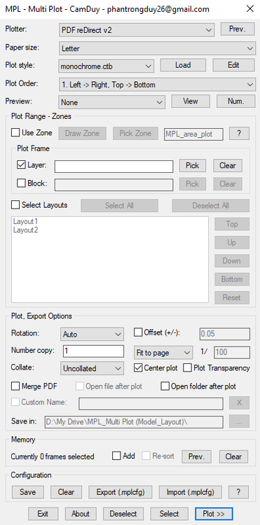
Hello everyone, I've just finished developing MPL (Multi Plot Layout/Model), a free AutoLISP tool that helps you batch print drawings in AutoCAD. Main Features MPL includes all the essential functions found in other batch plotting LISP tools, plus several improvements: Smart and intuitive DCL interface Merge all plots into a single PDF (no additional software or virtual PDF printer required) Automatically open the output file or folder after plotting, with customizable file name and save location Zone-based plotting – organize messy drawings and print them in the correct order based on defined zones Batch plot multiple layouts – rearrange the printing order of layout tabs without dragging the tabs at the bottom of AutoCAD Print Preview mode Add Selection feature – easily add more drawings to the current print list without starting over Export/Import plot configuration for quick reuse Download and user guide: https://drive.google.com/drive/folders/1WwmkXVgHFWTy8zIhARJYCH_G2OC2A_3D?usp=sharing Feel free to download it, give it a try, and let me know your feedback. Your suggestions will help improve MPL even further!
-
CamDuy joined the community
-
 Kamri joined the community
 -
Beyond APPLOAD: A local script manager for those of us with too many LISPs
VicoWang replied to VicoWang's topic in AutoLISP, Visual LISP & DCL
Hi BIGAL, First off—huge apologies for the double post! I originally stumbled across that 2007 thread, dropped a reply, and then realized it would be much better to create a dedicated thread so I could properly attach the .vlx file without hijacking the old discussion. Definitely a newbie mistake on my end, and I completely understand if the Admins merge or delete the old reply to keep the board clean. Thanks for the heads-up! I just went back and read your comment on that older post regarding your Install.lsp method. Extracting a ZIP natively via LISP COM objects, automatically creating directories, and injecting Support paths and CUIx menus is an incredibly resourceful and clever solution! It proves we've all been battling this exact same deployment nightmare for decades. Actually, your Install.lsp workflow is basically the spiritual predecessor to what I built with VedaCAD. The main difference is that instead of moving physical ZIP files, VedaCAD relies on pure mapping logic: At the atomic level, a 6-character VCID resolves a single asset. To migrate a whole PC, it simply compiles a list of those VCIDs into a lightweight config profile to batch-restore your entire setup. Scaled up for enterprises, it dynamically syncs environments based on user permissions. The engine handles all the file routing natively in the background. Since you clearly have a deep history with this community (20k+ posts is incredible), I actually have a question for you: Historically, the vast majority of AutoLISP routines and CAD tools have been strictly local. From your perspective, how far has the landscape evolved regarding web-connected or cloud-synced plugins? Are there many developers successfully exploring REST APIs or cloud-fetching inside AutoCAD nowadays, or is the community still heavily leaning toward local, air-gapped deployments? I'd genuinely love to hear your thoughts on where the ecosystem is heading. -
Dynamic blocks with Dynamic text and count
BIGAL replied to Shri95's topic in AutoCAD Drawing Management & Output
Yes need a much better realistic sample dwg with say a couple of different scenarios, array,non array and so on, even different lengths. There is a way of getting array info, you read the 1st object for properties, then the numbers in the row and column values. -
Beyond APPLOAD: A local script manager for those of us with too many LISPs
BIGAL replied to VicoWang's topic in AutoLISP, Visual LISP & DCL
You have posted twice about the same topic, as a newbie here there is no need to do that, Admin may decide to merge your two posts together. Made a comment in other post about installing new software. -
Migrate settings to new computer
BIGAL replied to hydrojock's topic in AutoCAD Drawing Management & Output
Did something similar but used lisp and wrote a Install.lsp it does just that makes directories, installs menu's, adds support paths. It uses a ZIP file which contains all your files etc lsp, fas, vlx mnu, cuix and so on, the unzip is does via lisp. So you just send two files to an end user drag the lsp onto CAD and your then asked where is the saved zip file. I did it that way as did not have access to a make install software.