Search the Community
Showing results for tags '3d'.
Found 17 results
-
 Hello, I want to collect detailed information about all faces of a `3DSOLID` without exploding or modifying the original solid. For each face, I would like to obtain information such as: * Face area * Face type, such as planar, cylindrical or curved * Boundary edges of the face * Length of each edge * Start and end points of each edge * Which edges are shared by two adjacent faces * Which faces are connected to each other through a common edge * The angle between adjacent faces * Face normal direction, where available Ideally, I would like to store the result in a structured form similar to: Is it possible to retrieve this topology directly using AutoLISP or Visual LISP without using `EXPLODE`? Would this require the AutoCAD .NET BRep API or ObjectARX, or is there an existing AutoLISP approach? Any examples, references or recommended methods would be helpful. Thank you.
 -
If you're just starting out with 3D in AutoCAD, this looks like a good tutorial. It shows off the power of AutoCAD to do some amazing things with relatively little effort. Follow along as the instructor draws a four-story apartment building and renders it.
-
Hello, I've been asked to make facade views from a survey in 3D. I have the house in 3d lines and i would like to extract the front-, left-, right- & back view of the facade. i used to do this by redrawing in an other file, but there has to be an easy way to "extract" that view. 1245337672_3dhouse.dxf
-

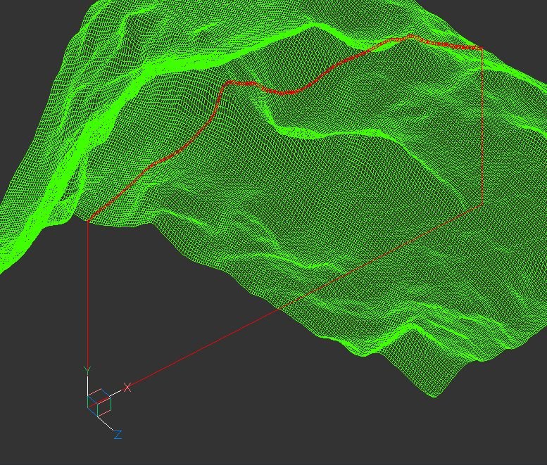
terrain Cross section of the 3D terrain
Andrej Skvarca posted a topic in AutoCAD 3D Modelling & Rendering
Hi guys, I've created an AutoLisp app which creates a cross section of the 3D terrain grid. The terrain can consists of raw AutoCAD entities: MESH / POLYFACE MESH / POLYGON MESH (one or more, even combined). As an author, I will be grateful for any comment, especially suggestions for improvements and developments. Andrej Skvarca TERRAIN_CROSS_SECTION.fas
- 12 replies
-
- 1
-

-
- mesh
- polyface mesh
- (and 10 more)
-

Slope design parking lot/water shed
Lippens Infra posted a topic in AutoCAD 3D Modelling & Rendering
Hello, By lack of plans, it has fallen upon me to design the slope of a parking lot. They HAVE to use water-permeable asphalt. The owner doesn't believe it will last and therefore he wants all water to evacutate towards 2 points. The area is 1.500m². The points are on the outside of the parking lot. Towards one point, we are allowed to use some kind of gutter. In the DWG the 3 buildings are red, the black lines are fixed in height, the green ones are not. The "gutter" is pink. the two points where all the water needs to flow towards are apointed with circles. These points are already the lowest points by nature. Is there a tool or trick to make slopes towards those points or do i need to calculate the slopes manually and use some trial and error? Thanks in advance! design parking lot.dwg -

How to select a "loft" surface via lisp to thicken
Hachi posted a topic in AutoLISP, Visual LISP & DCL
Hey guys! I'm trying to write a lisp that creates a 3D reducer. Once I create the 3D surface via command "_Loft" it remains to create a 3d solid body with the "thicken" command. I can't select the 3D loft surface. Can anyone help with this? Thanks in advance for the answers! Here is my code: (defun c:ccs (/ DK DN L P1 P2 P3 P4 RK RN S NS) (setq Dn (getreal "Adja meg a nagyobb vezeték külső átmérőjét:")) ; Give me the biger pipe diameter (setq Dk (getreal "Adja meg a kisebb vezeték átmérőt:")); give me the reduced diameter (setq L (getreal "Adja meg az átmenet hosszát:")); give me the length in which have to be reduced (setq s (getreal "Adja meg a falvastagságot:")); give me the thickness of the pipe (setq Rn (/ Dn 2)) (setq Rk (/ Dk 2)) (setq ns (min s (- 1))) (setq p1 '(0 0 0)) (setq p2 (list 0 0 L)) (setq p3 (polar p1 0 Rn)) (setq p4 (polar p2 0 Rk)) (setq p5 (polar p3 (/ pi 2) Dn)) (setq p6 (polar p1 pi Dn)) (command "_Circle" p1 Rn "") (command "_Zoom" "_All" "") (command "_Circle" p2 Rk "") (command "_Zoom" "_All" "") (command "_loft" p3 p4 "" "") (command "_select" p5 p6 "") ;(command "_THICKEN" ns "") (princ) ) -

Extracting frame lines from 3D mesh or object
Mugna101 posted a topic in AutoCAD 3D Modelling & Rendering
Hello people! Im using autocad 2018. I need to extract the frame lines from 3d meshes (i think its called a mesh but im not sure) I have attached an example file. Is there a way to automatically extract the outer lines so i could erase the rest and be left with only its frame? If there isnt any automatic way, how can i do it with the least amount of effort? its really hard to use a 3d poly and manualy frame itScan 3 (1).rar -
Hello, I have a file attached. It's the design for a yard. I want to annotate the slope of the planes. I could draw a line and annotate the slope of that line as well. Is there a lisp program able to calculate the slope for planes/lines drawn in 3D? Thanks in advance. enveloppe ontwerp met afloop naar straat1.dwg
-

Fastest way to have Quality elevation renderings
Brittney posted a topic in AutoCAD 3D Modelling & Rendering
Situation: I have hundreds of 2D house elevations that I need to have rendered "high (V-Ray) quality". Drawings are all 2D and current software im using is Softplan and Autocad. Im very proficient in autocad and I can draw them up 3D if I need to. For time purposes can I do this without having to draw 3D? Is there a add on for Autocad to make for better rendering? Should I use V-Ray? Should I convert to Revit then use V-Ray? What is the fastest way to do this? Id like to use the software I have but I want high quality. So im prepared to take on another software to achieve this. Attached is what im looking to accomplish. Thanks!
-
could you please recommend me some basic tutorial to learn how to use Auto Plant 3D? I never heard of this? is this the same as AutoCAD but drawing 3D? greatly appreciated.
-
Hello all - I'm jim - New to forum, and auto cad. Over the last few weeks ive been using this site and others to learn AutoCad. I have gleaned lots of useful information however i'm struggling with UCS rotations/ Drawing 3D in a lsp. I'm half way through developing my first lsp that calculates the difference in X,Y,Y. It then draws lines showing deviation directions (for example deviation from design). X and Y devition lines seem to be working ( not fully tested negative coordinates yet) but I cannot resolve the Z line. I have highlighted area that is causing problems. and have attached a screen dump of current results. I know it is probably somthing simple I am missing, but I think i have been looking at the problem t0o long, with too much autocad inexperience If anyone has any ideas or pointers please let me know. Regards JM ;Written by JM 2019 ;STILL UNDER CONSTRUCTION (defun rtd (r) (/ (* r 180.0) pi)) ;Angle conversions (defun dtr (d) (/ (* d pi) 180.0)) ;Angle conversions (defun c:delta (/ p1 p2 x1 x2 y1 y2 z1 z2 xp yp zp dx dy dz coorddiff Tolerence) (command "_UCS" "World") ;Ensure WCS is current (setq osm (getvar "osmode") ocmd (getvar "cmdecho") textStyle (getvar "textstyle") ) ;(setq Tolerence (getdist "\nTolorence in mm : ")) (while (setq p1 (getpoint "\nPick Design Position: ")) (setq x1 (car p1)) (setq y1 (cadr p1)) (setq z1 (caddr p1)) (setq p2 (getpoint "\nPick Asbuilt Position: ")) (setq x2 (car p2)) (setq y2 (cadr p2)) (setq z2 (caddr p2)) (cond ((<= x1 x2) (setq dx (rtos (- x2 x1))) (setq xp (polar p2 (dtr 0) 50)) (command "line" p2 xp "") ) ;_ end of the first condition x ((> x1 x2) (setq dx (rtos (- x1 x2))) (setq xp (polar p2 (dtr 0) -50)) (command "line" p2 xp "") ) ;_ end of the first condition x ) ;_ end of cond statement for X (cond ((<= y1 y2) (setq dy (rtos (- y2 y1))) (setq yp (polar p2 (dtr 90) 50)) (command "line" p2 yp "") ) ;_ end of the first condition y ((>= y1 y2) (setq dx (rtos (- y1 y2))) (setq yp (polar p2 (dtr 90) -50)) (command "line" p2 yp "") ) ;_ end of the second condition y ) ;_ end of cond statement for y ;**********************************************************Rotation Causing 3D Line issue? (cond ((<= z1 z2) (setq dz (rtos (- z2 z1))) (command "_UCS" "y" -90) (setq zp (polar p2 (dtr 180) -50)) (command "line" p2 zp "") ) ;_ end of the first condition z ((> z1 z2) (setq dz (rtos (- z1 z2))) (command "_UCS" "y" -90) (setq zp (polar p2 (dtr 180) 50)) (command "line" p2 zp "") ) ;_ end of the second condition z ) ;_ end of cond statement for z ;**********************************************************Rotation Causing 3D Line issue? ;;Displayes co-ordinates (command "_UCS" "World") (setq coorddiff (strcat dx "," dy "," dz)) (command "text" "j" "c" p2 25 -45 coorddiff) ) )
-
I was hoping someone in the community could help me out. I've found a design for some 3D printed Mickey Ears that I really like that I'd like to import into Tinkercad. The problem is the file has too many pieces and Tinkercad won't import it because it's too complicated. I've tried to join in AutoCAD, but I'm a novice, and when I try, it finds errors and won't join everything into one, simpler, object. If anyone could give me some pointers or help me out, I'd really appreciate it. I've attached two files, one where I grouped all the objects, hoping it would then join (to no avail), and the other one is everything separate. Thanks in advance to any who could offer assistance. -Kent Blank Ear Grouped.dwg Blank Ear.dwg
-
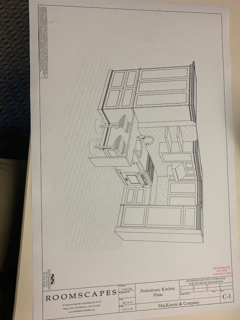
My company doesn't do much 3D, We would like to, we have the latest "Auto-CAD Architecture" and we primarily do kitchens and baths. Our typical presentations for clients consist of floor plans and elevations that we typical color w/ markers. It is a beautiful classic presentation. I'm looking for the best training options to learn how to create a plan like attached. The guy that can do this type of drawing is always busy and doesn't have a ton of time to teach it, and we don't utilize this type of drawing nearly enough. I want to learn how to do it quickly and efficiently to become a better asset to my company. where can i get some Kitchen 3d centric AutoCAD Architecture training. TIA
-
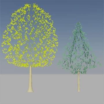
Version 1.0.0
1,674 downloads
3D Trees (Deciduous and Coniferous) These 3D tree models are compatible AutoCAD R14 and higher. All drawings are suitable for use as blocks within AutoCAD. The trees have been drawn at an appropriate size for a young, standard tree, in metres. To insert a tree at the default size, simply use the default insert scale factor (1). You can always change the X,Y and Z scale factors later using the Properties command. The trees are all drawn on appropriate layers and are unique to each tree so that canopy colour can be changed independently when more than one tree symbol is used in the same drawing. In each case, the insert base point is at the base of the tree trunk in the centre of the tree. -
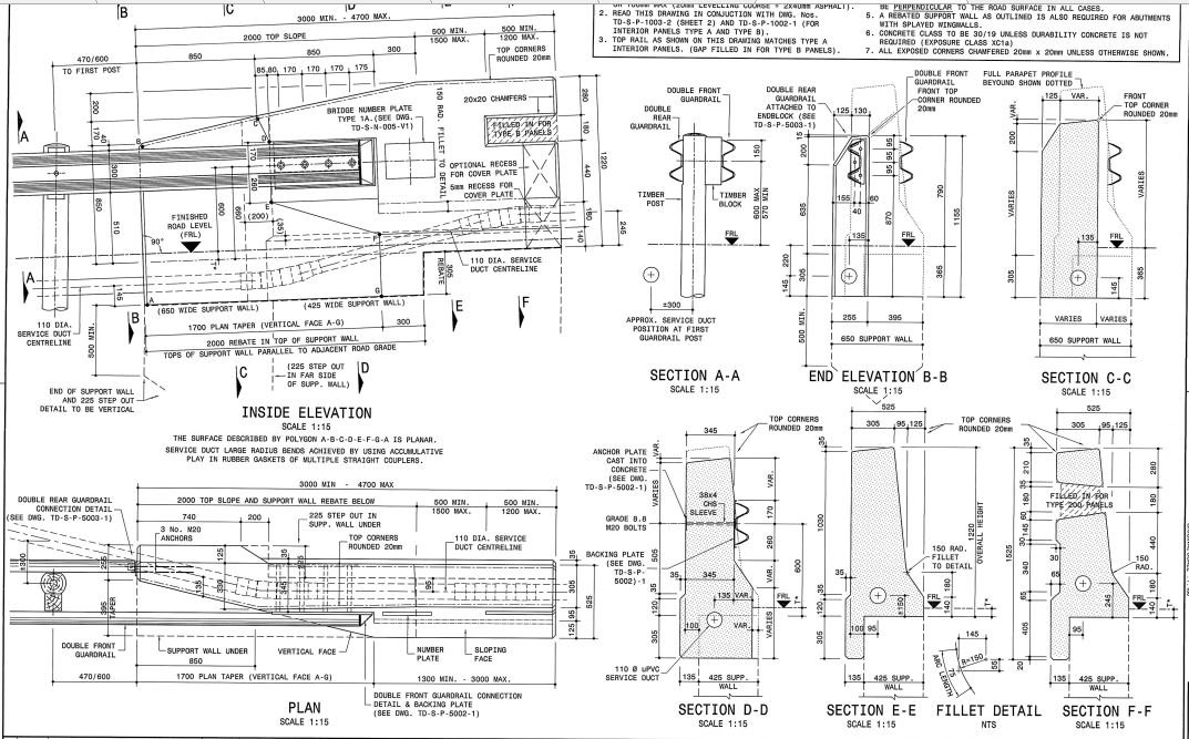
Good Morning all i am currently busy with a bridge for our structural department, and i need to model a Bridge End Block. i have attached a few images of the said End Block How would i go about modeling such an intense item ? The reason for the model rather than just linking in a CAD 2D view, is they require the End Block to be Reinforced..
-
I'm having a hard time: I'm creating a middle line in the center of a road route, to verify the distance traveled by trucks. To do this, I create a 3dpolyline by connecting the edges of the path and then create a 3D POLYLINE by clicking on the midpoint of each polyline to draw a median route. As they are many, it is being a complicated job, since I have to click on the midpoint of each one to generate the 3D line that I need. Is there any lisp that can already do this, remembering that it needs to be 3D?
-

Panning in Orthographic Views shows 3D details.
Engr Varsi posted a topic in AutoCAD 3D Modelling & Rendering
Hi, Being new to this forum, I have first tried the search option to look for similar problem which I couldn't. Problem: Panning in Top, Left or any other Orthographic View, shows the hidden or out plane details. Please see in this figure. This is a circle extruded to height of 45ft and I panned in the TOP View to the right This is when I panned it to upper left corner. Desired Output: I just want it to be panned as in true Orthographic Projection. As shown in the figure below. Thanks.