All Activity
- Past hour
-

Insert a copy of the block at the specified point. CopyRenameBlockV1-5.lsp /Lee Mac/
CamDuy replied to Nikon's topic in AutoLISP, Visual LISP & DCL
CopyRenameBlockV1-5_byCamDuy.lsp Try using this file. @Nikon -
Free Multi Plot Lisp – Fast Batch Printing for AutoCAD, BricsCAD & ZWCAD | Model/Layout, Zone Plotting & PDF Merge
CamDuy replied to CamDuy's topic in AutoLISP, Visual LISP & DCL
Thank you for your feedback. I will update the version for 2014 and earlier. -

Free Multi Plot Lisp – Fast Batch Printing for AutoCAD, BricsCAD & ZWCAD | Model/Layout, Zone Plotting & PDF Merge
VicoWang replied to CamDuy's topic in AutoLISP, Visual LISP & DCL
When I develop vedacad, it is different. My main coding and compilation are done on 2006, avoiding the use of advanced features and ensuring that vedacad can punch through all versions of 2026 from 2006. However, it is true that most people have already done their daily work on the higher version. My test environment is 2006,2014 and 2022. -
Free Multi Plot Lisp – Fast Batch Printing for AutoCAD, BricsCAD & ZWCAD | Model/Layout, Zone Plotting & PDF Merge
CamDuy replied to CamDuy's topic in AutoLISP, Visual LISP & DCL
Drop me an email "phantrongduybn@gmail.com" I'll send it to you. -
Free Multi Plot Lisp – Fast Batch Printing for AutoCAD, BricsCAD & ZWCAD | Model/Layout, Zone Plotting & PDF Merge
CamDuy replied to CamDuy's topic in AutoLISP, Visual LISP & DCL
I think AutoCAD 2014 is too old; versions from 2015 onwards work just fine. because it was built on a higher version. -

Free Multi Plot Lisp – Fast Batch Printing for AutoCAD, BricsCAD & ZWCAD | Model/Layout, Zone Plotting & PDF Merge
Nikon replied to CamDuy's topic in AutoLISP, Visual LISP & DCL
The link doesn't work for me, could you please attach the archive? - Today
-
Free Multi Plot Lisp – Fast Batch Printing for AutoCAD, BricsCAD & ZWCAD | Model/Layout, Zone Plotting & PDF Merge
VicoWang replied to CamDuy's topic in AutoLISP, Visual LISP & DCL
I tried using it with VedaCAD, and it didn't work in 2014 but ran perfectly in 2022. I thought it was a problem with the VedaCAD proxy, so I loaded the VLX file from the cache separately, and it still didn't work in 2014 but could run in 2022. Does this plugin have a minimum version requirement? -
 povilasltu joined the community
 -
 MAQBOOL AHMED joined the community
 -

Yet another block manager for BricsCAD
Danielm103 replied to Danielm103's topic in Application Beta Testing
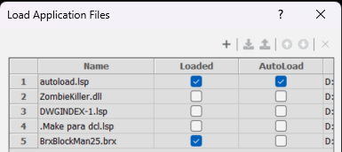
Also, make sure the xrc file is in the same folder, if you moved the BRX -
Yet another block manager for BricsCAD
Danielm103 replied to Danielm103's topic in Application Beta Testing
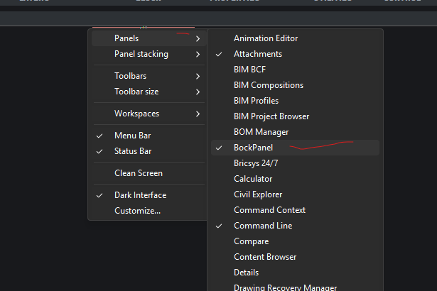
You should see a version number on the command line. It’s a panel, it should sit next to the properties panel, right click on Bricscads task bar and look for the new panel
-

Yet another block manager for BricsCAD
BIGAL replied to Danielm103's topic in Application Beta Testing
downloaded zip copied v25.brx and src to a known support path Appload D:\Alan\LISP\BrxBlockMan25.brx successfully loaded. Type blockman and nothing happens ? Any ideas, running twin screens ??
-
@CivilTechSource "lisp detects a new polyline that touches the rest of the road network it would add it." yes could be done. Not sure if add a road pline then just run the program I posted would still do what you want. Change the ssget to have filters so looks for *line on correct layer. Yes I tend to use defuns for a task rather than just put all the code into one big step by step. Re check against existing and new plines I removed a look for defun it basically would get a Road pline then look for the mtext at the mid point, it uses a defun that takes advantage of SSGET "F" so makes say a 8 sided point list, this detects the mtext if its at centre of pline.. So the answer to your question may be add roads then search for unlabelled. So need a second step to (defun ahfindlast Starting here (princ "\nSelect all polylines and lines that make up the new road network: ") (setq road-ss (ssget '((0 . "LINE,*POLYLINE")))) ; need to change this adding a layer name ; compare the two lists of has label and remove enetity when exists from the slection Road-ss I did start writing my code that way, may go back to it. yes would then make a list of unlabelled roads. Say version 2. The look for defun use a point and make a list of points using (polar pt ang dist) repeat say 8 times with the angle increasing (/ pi 4.0) then the (ssget "F" lst with filters) think circle.
-
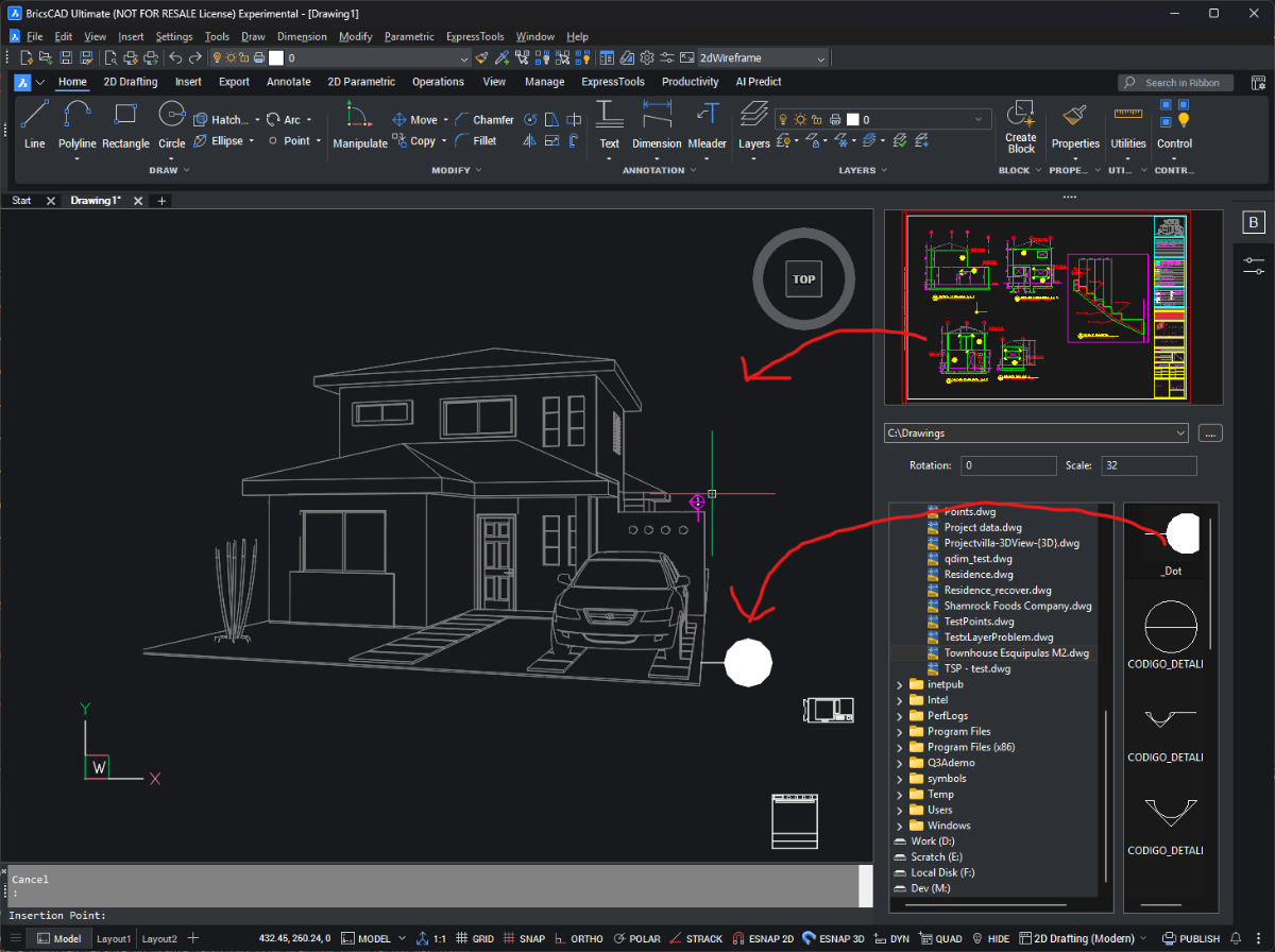
I posted this at the swamp, this is pretty cool Proof of concept (V25, V26, V27Beta) - appload BrxBlockManXX.brx - type blockman at the prompt - select a drawing from the directory control - double click or drag a block from the List control to the current drawing - double click the main preview to insert the whole drawing - click the open folder button to add your favorite folder(s) - use the dropdown to navigate to a favorite folder - right click on a dwg to open it let me know if it crashes lol Release.zip
-
Ok as the block supplied has a hard coded ID of an object in the field statement, then this block is somehow being made for every area that is labelled. With a change to the objectId relevant to each area chosen. So are you getting this from some one else ? Or you just have a make a new block program labelling the area ? If you have a program then hopefully its just a simple add a do you want 0 1 2 or 3 for precision. This is fieldcode for the mtext, the dynamic block adds an extra hurdle. "\\A1;{\\H1.42857x;%<\\AcObjProp Object(%<\\_ObjId 1668905712>%).Area \\f \"%lu2%pr3\">%m\\H0.7x;\\S2^;\\H1.42857x; \\P\\H1x;mText }" If you want 2 decs then change the pr3 to pr2.
- Yesterday
-
Hi all, Thanks again for all the help and feedback. @GLAVCVS - Would it not cause more issues condensing the prompt of selecting the polyline & start point will cause in some cases error if we are at a junction and we have two polylines opposite each other? Thanks for the geometric mid-point tip! @BIGAL - Re-layer check, I tested it on a blank drawing without that layer and it worked, no crash. I do like the idea of creating small lisp functions for repetitive stuff. I did not understand the " pline vertice points, thanks to lee--mac." Does making a list of entities is less process intensive? How did I not think about adding check if roads are numbered! Thanks that is handy and very nice to have. So I have a generic question, when creating a lisp which approach is best: - Create it as simple as possible OR - Develop it so its almost its own mini app? (e.g. we could feature to auto-update road numbers feature by specifying the road centreline layer, so if the lisp detects a new polyline that touches the rest of the road network it would add it). Not sure if it will be any good, but I did start a github repo for lisps I create as I go. https://github.com/CivilTechSource/AutoCAD-Lisps-4-All
-
Beyond APPLOAD: A local script manager for those of us with too many LISPs
VicoWang replied to VicoWang's topic in AutoLISP, Visual LISP & DCL
Hi zaphod, Thank you so much for testing it out and sharing this feedback! 1. Auto-filling Asset Name from File Name: Absolutely agreed! You’re 100% right—when you browse and select a file like AreaCalc.lsp, the system should intelligently parse (vl-filename-base) and automatically pre-fill "AreaCalc" into the Asset Name if the field is empty. This eliminates repetitive typing when adding a batch of local tools. We are incorporating this directly into the next build! 2. Defaulting Version to 0: Why we intentionally keep it blank. You bring up an interesting point, but keeping the Version field blank is actually a deliberate architectural design choice on our end. In VedaCAD's ecosystem, published version numbers are immutable once uploaded to ensure clean version tracking and hot-updates. If we pre-fill 0, a user adding a local script and casually clicking "Publish" would permanently stamp their cloud asset with version 0 without making a conscious choice. Leaving the field blank forces a brief pause, ensuring authors explicitly set a structured initial version (such as 1.0 or 1.0.0), which keeps the public ecosystem metadata clean and reliable for everyone. Really appreciate you taking the time to share these ideas—feedback like this helps us fine-tune both the user experience and the underlying discipline! Vico -

Beyond APPLOAD: A local script manager for those of us with too many LISPs
zaphod replied to VicoWang's topic in AutoLISP, Visual LISP & DCL
Nice Lisp VicoWang! This looks like a great solution to the dreaded startup suite, some suggestions; Is it possible to have the "Asset Name" be the file name by default? Could the "Version" field default to 0? -
 brien joined the community
 -
 bbaze joined the community
 -
Please see attached I have a Block and mText Field linked to the same Boundary. currently the mText works great but would like to have the option of amending the precision within the block also. Field Precision.dwg
-
To change a field in a block you would need to iterate through all the objects defining that block so finding a text or attribute object within, then update, a text is a singular object. Not sure with a block can do just one or need to edit the block definition. This will fail for a block (setq value_string (vla-FieldCode Obj) nbs 0) you need to check each individual entity as Obj. It may be best to post a sample dwg, with text and blocks.
-
Updated code above it now looks for existing labels and gets the last number and adds 1. Still a couple of things to improve but will leave that to @CivilTechSource to look at. I added a get angle at point defun.
-
This is great, I really like the code from Tsuky. Thankyou for this and works great for stand alone text/mtext. Out of curiosity I can select blocks by adding ....,INSERT") to the ssget function. Just wondering if it can be amended to change the precision of fields within selected blocks as well as stand alone text? (vl-load-com) (defun c:change_prec ( / ss AcDoc Space prec_source ktarget n ename Obj value_string nbs tmp_nbs) (princ "\nSelect MText.") (while (null (setq ss (ssget (list '(0 . "*TEXT,INSERT") (cons 67 (if (eq (getvar "CVPORT") 1) 1 0)) (cons 410 (if (eq (getvar "CVPORT") 1) (getvar "CTAB") "Model")) ) ) ) ) (princ "\nAren't MText or Text!") ) (setq AcDoc (vla-get-ActiveDocument (vlax-get-acad-object)) Space (if (= 1 (getvar "CVPORT")) (vla-get-PaperSpace AcDoc) (vla-get-ModelSpace AcDoc) ) ) (vla-startundomark AcDoc) (initget 1 "0 1 2 3 4 5 6 7 8 9 10 11 12 13 14 15 16 Current") (setq ktarget (getkword "\nPrecision of target number [0/1/2/3/4/5/6/7/8/9/10/11/12/13/14/15/16/Current]?: ")) (repeat (setq n (sslength ss)) (setq ename (ssname ss (setq n (1- n))) Obj (vlax-ename->vla-object ename) ) (setq value_string (vla-FieldCode Obj) nbs 0) (cond ((vl-string-search "%<\\" value_string nbs) (while nbs (if (setq nbs (vl-string-search "%pr" value_string (setq tmp_nbs nbs))) (setq prec_source (itoa (atoi (substr value_string (+ nbs 4) 2))) value_string (vl-string-subst (if (eq ktarget "Current") (strcat "%pr" (itoa (getvar "LUPREC"))) (strcat "%pr" ktarget) ) (strcat "%pr" prec_source) value_string tmp_nbs ) nbs (1+ nbs) ) ) ) (vlax-put Obj 'TextString value_string) ) ) ) (vla-endundomark AcDoc) (prin1) )
-
North direction in AutoCAD drawing does not match my real-world compass direction
BIGAL replied to CHICHA's topic in AutoCAD General
@CyberAngel this may be useful, it is what we used every day, we had a JPG and a JGW file. rescale image.lsp - Last week
-
 Liubomyr changed their profile photo
 -
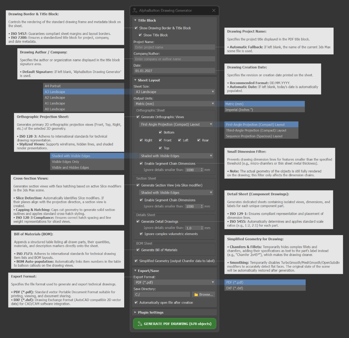
Hi everyone! As an architect and 3D artist, I developed AlphaButton Drawing Generator — a native 3ds Max plugin designed to automate the creation of technical CAD drawings, vector PDFs, and editable 2D DXF files directly from the 3ds Max viewport in just 2 clicks: Select geometry ➔ Click Generate. Generate professional technical drawing sets in vector PDF and 2D DXF formats (compatible with AutoCAD, SolidWorks, Rhino, and major CAD/CAM software) directly inside 3ds Max 2025–2027 — no manual rebuilding required. How It Works — 2 Simple Steps: Select Geometry — pick the objects in your 3ds Max viewport. Generate PDF or DXF — click GENERATE PDF or GENERATE DXF. The plugin automatically builds the layouts and opens the final file for instant review, printing, or CAD/CAM fabrication. Designed as a perfect fit for: • Client Presentations & Design Reviews — clean concept drawings and realistic shaded layouts directly from your viewport. • Furniture Manufacturing & Joinery — isolate individual parts and generate clean, exact dimensions for local, CNC, or industrial production. • Workshop & Assembly Documentation — component blueprints, section cuts, and structured bills of materials (BOM) for the shop floor. Compliance with Engineering & CAD Standards: • Vector PDF & 2D DXF Export — exports production-ready vector PDFs for print and presentation, or fully editable 2D DXF files (AutoCAD DXF R2007 / AC1021 format or newer) for AutoCAD, SolidWorks, Rhino, and CAM cutting software. • Dual Unit Systems — full support for both Metric (mm) and Imperial (in) units with 1:1 real-world scale accuracy. • Projection & Section Views (ISO 128 / ASME Y14) — 3 visual presentation styles: Shaded with Visible Edges, Visible Edges Only (classic CAD blueprints), and Visible + Hidden Edges (dashed lines for internal cavities and joinery). • Drawing Borders & Title Blocks (ISO 5457 / ISO 7200) — automated layout borders, project metadata, author signatures, and revision dates. • Detail Sheets (ISO 129-1 / ISO 5455) — unique components auto-extracted to dedicated individual drawings with standard scale ratios (1:1, 1:2, 2:1, etc.). • Automated Bill of Materials (ISO 7573) — structured specification tables listing all parts, quantities, and dimensions, automatically linked to drawing balloon callouts. Video Demos of the Workflow: • 2D DXF Export & CAD Import: Try it free for 14 days (One click, no email, no registration, no credit card required): Download Free Trial on Patreon: System & Geometric Requirements: • Autodesk 3ds Max: 2025, 2026, or 2027. • Geometric Compatibility: Works best with native 3ds Max geometry (primitives, parametric extrusions, Editable Poly/Mesh) with clean smoothing groups and active modifiers. Avoid organic/sculpted geometry or collapsed booleans for detail dimensioning. I would highly appreciate your honest feedback, testing results, or constructive critique from the CADTutor community! Thank you for your time and support! Best regards, Liubomyr Hrytsai Creator of AlphaButton Drawing Generator Patreon: https://www.patreon.com/AlphaButton AlphaButton_Sample_Drawing_Set_(ASME_Imperial).pdf AlphaButton_Sample_Drawing_Set_(ISO Metric).pdf
-
Liubomyr joined the community
-

North direction in AutoCAD drawing does not match my real-world compass direction
CyberAngel replied to CHICHA's topic in AutoCAD General
We use Civil 3D, so we have more tools. Typically we get a batch of points in state plane coordinates. That means you can draw a line anywhere along the Y axis of those coordinates and get a fairly accurate North. It's not totally accurate because, obviously, that same vertical line is parallel at the ends of your state, which can be hundreds of miles apart. That's what a datum is for, I guess, to reconcile the grid with the surface of the Earth. This seems like a simple problem, but it's a nightmare if you don't have enough data. What I'll typically do is get a screen grab from an aerial map, making sure it's oriented to North, at a known scale, with a graphic scale included. Add that image to the drawing as an Xref at rotation 0. Scale it so that the graphic scale is correct. Then the fun part: find locations that match your drawing and line them up. Then the nightmare part: keep in mind that aerial images aren't always taken from directly above that area, so there's going to be some skew--and you have no way of knowing what that skew factor is. Sometimes you have to decide which points are more important to get right and let the rest be off. There's a command named ALIGN, which is very handy here: pick two or three points from the image and the corresponding points from the drawing; decide whether to scale the image; and watch the magic. With a drone you could get an image from a known spot, but not everyone has access to a drone. Other strategies: look for benchmarks in your drawing. In the US there's a system of markers placed by the Geodetic Survey. Surveyors often begin their locating from a benchmark, geodetic or otherwise. What you're trying to do is find three points that will define a plane. The other strategy only works if you know some property corners or can locate them: get a plat (not a deed, those cost money) for a piece of property. It will include bearings and distances for each border line. That gives you distance and direction between your property corners, so you can define your plane. Of course all these strategies depend on the drawing being in World UCS. You sometimes find a Plan North, and you can create a UCS to match that. Orienting the drawing to some other UCS will lead to problems down the line, I've been there. -
 pranayacntos joined the community
 -
Had a play took a different tack, still needs some more improvements. The angle returned at a pline point determines wether the label goes below or on top that needs to be looked also. But it does use a Mid point method. needs localising of variables etc. Call it version one. ; https://www.cadtutor.net/forum/topic/99216-name-my-roads/ ; label roads by CivilTechSource Jukly 2026 ; Modified by AlanH July 2026 ;;; ========================================================================= ;;; USER CONFIGURATION - EDIT THESE VARIABLES EASILY ;;; ========================================================================= ;;; Check does layer exist (defun chklay (layn color ltype / ) (command "-layer" "make" layn "C" color "" "LT" ltype "" "") ) (defun alg-ang (obj pnt) (angle '(0. 0. 0.) (vlax-curve-getfirstderiv obj (vlax-curve-getparamatpoint obj pt ) ) ) ) ;; Parse Numbers - Lee Mac ;; Parses a list of numerical values from a supplied string. (defun LM:parsenumbers ( str ) ( (lambda ( l ) (read (strcat "(" (vl-list->string (mapcar '(lambda ( a b c ) (if (or (< 47 b 58) (and (= 45 b) (< 47 c 58) (not (< 47 a 58))) (and (= 46 b) (< 47 a 58) (< 47 c 58)) ) b 32 ) ) (cons nil l) l (append (cdr l) '(())) ) ) ")" ) ) ) (vl-string->list str) ) ) (defun ahfindlast (rdents / x road-entity txt newnum) (setq x 0 global:road-counter 0) (while (< x (sslength rdents)) (setq road-entity (ssname rdents x)) (setq txt (cdr (assoc 1 (entget (ssname rdents x))))) (princ (strcat "\npline already labelled " txt)) (setq newnum (car (LM:parsenumbers txt ))) (if (= newnum nil)(setq newnum 1)) (if (> newnum global:road-counter)(setq global:road-counter newnum)) (setq x (1+ X)) ) (setq global:road-counter (1+ global:road-counter)) (princ) ) ;;; MTEXT CREATION FUNCTION (WITH ROTATION & READABILITY LOGIC) (defun action-label-road (road-entity number road-text-layer road-text-color road-text-height pt / ang readable-ang ) (setq ang (alg-ang road-entity pt)) (if (and (> ang (/ pi 2.0)) (<= ang (* pi 1.5))) (setq readable-ang (+ ang pi)) ; Flip 180 degrees if necessary (setq readable-ang ang) ; Keep original angle otherwise ) (setq pt (polar pt (- (/ pi 2.0) ang) road-text-height)) (entmake (list (cons 0 "MTEXT") (cons 100 "AcDbEntity") (cons 8 road-text-layer) ; Applies your layer (cons 62 road-text-color) ; Applies your color (cons 100 "AcDbMText") (cons 10 pt) ; Places text at the middle of the road (cons 40 road-text-height) ; Applies your text size (cons 50 readable-ang) ; <--- APPLIES CALCULATED READABLE ROTATION (cons 71 5) ; Forces "Middle Center" alignment (cons 1 (strcat global:road-prefix " " (itoa number))) ; Text content ) ) (setq global:road-counter (1+ global:road-counter)) (princ) ) ;;; ========================================================================= ;;;;;;;;;; Starts here ;;;;;;;;;;;;;;;; (vl-load-com) ; Loads advanced geometry functions for handling polylines (defun c:NumberRoads ( / dist obj road-default-prefix road-ss road-sstxt user-prefix x) ; (setq road-text-height 2.5) ; How tall the road number text should be ; (setq road-text-layer "Road-Labels") ; The layer where the text numbers will go ; (setq road-text-color 2) ; Color index for the text numbers (2 = Yellow) (setq road-default-prefix "Road") ; The default name if you just press Enter (chklay "Road-Labels" 1 "Continuous") ; Does layer exist check (setq road-sstxt (ssget "X" (list (cons 0 "*text")(cons 8 "Road-Labels")(cons 410 "Model")))) (if (= road-sstxt nil) (alert "No existing labels ") (ahfindlast road-sstxt) ) (princ "\nSelect all polylines and lines that make up the new road network: ") (setq road-ss (ssget '((0 . "LINE,*POLYLINE")))) (if road-ss (progn (if (= global:road-counter nil)(setq global:road-counter 1)) (setq grc (getint (strcat "\nEnter new Road profile number eg " (rtos global:road-counter 2 0) " "))) (if (= grc nil) (princ) (setq global:road-counter grc) ) (setq user-prefix (getstring t (strcat "\nEnter road prefix <" road-default-prefix ">: "))) (if (= user-prefix "") (setq global:road-prefix road-default-prefix) (setq global:road-prefix user-prefix) ) (setq x 0) (while (< x (sslength road-ss)) (setq road-entity (ssname road-ss x)) (setq obj (vlax-ename->vla-object road-entity)) (setq dist (/ (vlax-get obj 'length) 2.0)) (setq mid-param (vlax-curve-getpointatdist obj dist)) ; road-entity number road-text-layer road-text-color road-text-height (action-label-road obj global:road-counter "Road-Labels" 2 2.5 mid-param) (setq x (1+ X)) ) ) ; progn ss (princ) ) ; if ss (princ) ) (c:NumberRoads) I am leaning towards making the input here much bigger rather than lots of setq's just set default values in the defun call. Or use a dcl to set values.
-
Beyond APPLOAD: A local script manager for those of us with too many LISPs
VicoWang replied to VicoWang's topic in AutoLISP, Visual LISP & DCL
Hi BIGAL, First off, thank you for sharing your perspective on how the community and your clients are handling the "cloud" today. It’s really insightful to hear where the landscape actually stands from someone with your experience. You’re spot-on that most people currently just map AutoCAD Support Paths to a static cloud drive folder. And that "In office" / "Out of office" dual-icon setup you mentioned? That is a brilliant piece of classic IT problem-solving! It perfectly captures the exact nightmare CAD Managers have dealt with for years when engineers take laptops to construction sites. Analyzing those classic IT workarounds highlights that the core deployment challenges in CAD haven't changed, but modern architectures give us new ways to tackle them. At their core, almost all traditional methods—whether passing local ZIPs or mapping static cloud drives—rely on static distribution. Once a file leaves the source, its connection is severed, inevitably leading to version fragmentation across the firm. This is exactly why we designed VedaCAD to provide dynamic lifecycle management through a "Cloud-Managed Local Sandbox", rather than just live cloud mapping. From an engineering standpoint, here is how we structured the technical measures to handle those specific scenarios: Solving the offline field scenario Mapping directly to a cloud drive introduces fragility—if the internet drops, CAD freezes. To prevent this, everything in our architecture physically runs from a local sandbox cache on the C drive. The client simply pings the server with a lightweight heartbeat. If an engineer opens their laptop on a site with zero Wi-Fi, the LISP kernel silently transitions into Offline Mode. They keep drawing seamlessly using their local cache until the configured offline grace period expires. No need for separate desktop icons. Managing binary updates and file locks When a developer patches a .vlx or .dll, expecting users to manually download and replace ZIPs leads to version fragmentation. We shifted this to a heartbeat-driven sync. When the server detects a version drift, the update is pulled into the sandbox. Depending on the workspace policy (Manual, Auto, or Enforced), the user either clicks to approve it, or the engine hot-swaps it silently in the background. To bypass Windows file locks on running binaries, the engine utilizes a backend .bak renaming trick to perform the in-place replacement without crashing CAD. Resolving subcontractor environment consistency How do we ensure that all subcontractors perfectly align with the drafting standards set by the general contractor, even down to the absolute uniformity of a single linetype color? We tackled this by building isolated containment fields we call "Project Arks". Instead of emailing ZIP files of CAD standards, a General Contractor can package their absolute drafting environment and issue a time-limited "Visa". When a subcontractor mounts it, their CAD temporarily mirrors the GC's standard. Crucially, if the GC updates a .ctb or other environment configuration files mid-project, the subcontractors pull the latest standard on their next heartbeat or upon manual sync, allowing the GC to monitor exactly which external terminals are lagging on outdated standards. Asset revocation and self-healing If a subcontractor's Visa expires, or an internal employee's device is unbound, the system relies on a zero-trust model. Upon the next ping, the engine executes a remote kill-switch, physically shredding the proprietary CAD assets from the local cache. Conversely, if a user accidentally deletes a cached plugin, the LISP reactor detects the loss via a native (findfile) check and instantly auto-fetches the replica from the cloud, ensuring the execution chain never breaks. It’s always a pleasure geeking out over deployment architectures with veterans. Thanks again for the great discussion! Cheers, Vico