Search the Community
Showing results for tags 'dxf'.
Found 22 results
-

Set MLeader to Existing MLeader Style via LISP
parkerdepriest posted a topic in AutoLISP, Visual LISP & DCL
Hello, I am trying to create a lisp routine that sets all existing MLEADERs to a certain pre-set MLEADERSTYLE, the equivalent of doing a Quick Select for Mleaders, and setting the style under the properties window. I was able to write a similar routine that selects all dimensions and sets them to a certain DIMSTYLE, using entmod and DXF code 3 for dimstyle. So far, I have not been able to find a group code for MLEADERSTYLE Any help would be greatly appreciated! (defun C:dimstylechange (/ ENTITIES NO_OF_ENTITIES SSPOSITION ENTITY_NAME OLD_ENTLIST NEW_STYLE NEW_ENTLIST) (setvar "CMDECHO" 0) (setq ENTITIES (ssget "X" '((0 . "DIMENSION")))) (setq NO_OF_ENTITIES (sslength ENTITIES)) (setq SSPOSITION 0) (repeat NO_OF_ENTITIES ;***CHANGE STYLE*** (setq ENTITY_NAME (ssname ENTITIES SSPOSITION)) (setq OLD_ENTLIST (entget ENTITY_NAME)) (setq OLD_STYLE (assoc 3 OLD_ENTLIST)) (setq NEW_STYLE (cons 3 "BCR 11x17")) (setq NEW_ENTLIST (subst NEW_STYLE OLD_STYLE OLD_ENTLIST)) (entmod NEW_ENTLIST) ;***CHANGE LAYER*** (setq OLD_ENTLIST (entget ENTITY_NAME)) (setq OLD_STYLE (assoc 8 OLD_ENTLIST)) (setq NEW_STYLE (cons 8 "DIM")) (setq NEW_ENTLIST (subst NEW_STYLE OLD_STYLE OLD_ENTLIST)) (entmod NEW_ENTLIST) (setq SSPOSITION (1+ SSPOSITION)) ) (command ".CHPROP" ENTITIES "" "C" "BYLAYER" "LT" "BYLAYER" "") (princ (strcat "\n..." (rtos NO_OF_ENTITIES 2 0) " Dimension(s) changed...")) (setvar "CMDECHO" 1) (princ) ) dimstylechange.LSP -
I need to convert a xml file into a .ply format. I started with a catproduct and I want to project that catproduct using a Virtek laser. In order to do so, I need a .ply and .cal files. How can I do that?
-
I have found the following at the swamp, however I would like to modify it to better suite my needs. All credits to Lyle Hardin for writing the awesome code. ;;; CADALYST 08/08 www.cadalyst.com/code ;;; Tip 2305: LeaderToMleader.lsp Leader to Multileader (c) 2008 Lyle Hardin ;;; Pick an old style leader and text to create a new mleader entity and erase the old leader and text. ;;; March/2008 (defun c:leadertomleader () (setq leader (entsel "\nPick Leader") ; pick leader leader2 (entget (car leader)) pt1 (dxf 10 leader2) ; get first point of leader layer (dxf 8 leader2) ; get layer of leader mtext (entsel "\nPick Text") ; pick text mtext2 (entget (car mtext)) pt2 (dxf 10 mtext2) ; get point of text text (dxf 1 mtext2) ; get ) ; setq (command "-layer" "s" layer "") ; set layer of leader picked to current (command "mleader" pt1 pt2 text) ; start mleader command (COMMAND "ERASE" mtext "") ; erase text picked (command "erase" leader "") ; erase leader picked ) ; defun (defun dxf(code elist) ; define dxf function (cdr (assoc code elist)) ;Finds the association pair, strips 1st element );defun So what I would like to do is instead of selecting the insertion point of the mtext as the second point, I would like to change it to the second point of the leader. I've done a little bit of digging around, but all I have found is that the dxf codes for the vertices are 10, resulting in a list: (10 -94274.8 121436.0 0.0) (10 -94274.8 121109.0 0.0) (10 -95313.2 121109.0 0.0) ...(and so on) Hence my question, how do I get the second vertex of the leader? Thanks in advance.
-

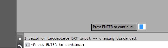
Invalid of incomplete DXF input -- drawing discarded
MarcS1989 posted a topic in AutoCAD Bugs, Error Messages & Quirks
Hello, This is my first forum post and I have been doing a lot of searching before coming here so please be nice! I'm having a problem when trying to open a DXF file in AutoCAD LT 2017, I'm getting an error saying: 'Invalid of incomplete DXF input -- drawing discarded' I have an issue with a drawing where there are lots of blocks and line types that can't be purged out. Normally with our drawings if you DXFOUT and DXFIN it then allows you to purge everything but when I get this error I hit a dead end. Unfortunately I can't upload the drawing itself here due to my companies data security policy but if you need any more details please ask and I'll see what I can do. Thanks! P.S. The file itself is saved in AutoCAD LT 2010 and I'm trying to open it in 2017, I've also tried 2013 but this gives me the same error message. All of our 25,000+ drawings are saved this way and we only have access to 2017 and 2013 versions of AutoCAD LT yet this error only shows on a small amount of drawings.
-

DWG to DXF, missing lines when plotting.
Revered posted a topic in AutoCAD Drawing Management & Output
Guys, I had to re-scale a drawing and convert it to DXF so we can use in our cutting machine. The problem is when I try to open the DXF file on our factory computer there are missing some lines. But when I open the file on my computer, it is perfect. Do you guys now if this is a AutoCAD error when converting the file to DXF or its a problem with our factory's computer ? -
Hi folks. Have been trying to make s lisp code for a simple task but turned out that it might not be so easy. I found lots of information but not this one. So i'm asking if this is even possible to do. I have a block and it has many entities. The block has a name but all the (2-3) entities have different color. I'm trying to change the entity color without exploding the block and change the entity name. This part is ok and i even found a good solution for this. However the problem is that i have to rename also the main block regarding the selected color for the entity. I have 5-10 options for color. (112=blue, 113=red etc.) So the final block name should turn out as 123456-112. I know how to find the block name and change but when i go deep into entities then i dont have the DXF code for the original block name. So here i am in an endless loop. Can someone assist or show me some directions how to manage with this? Thanks.
-
I hope this i the right place for this post. I have gotten a Dxf and a pdf of the same file, but when I open the Dxf file the file do not look right as it does on the pdf, the one who sendt me these files, send me a screenshot of the opend dxf file on his computer, and there it look just fine. anyone know a solution for this problem? Thanks opfront
-

convert cloud of points or mesh into surface
fdefrance posted a topic in AutoCAD 3D Modelling & Rendering
Hello, I am using Matlab to create a surface I import into Autocad Mechanical 2015. Matlab uses a library to convert a matrix into a .dxf 3D surface. Depending on the option, the surface is either a cloud of points, or made of triangles or square patches (linking the points). (files attached) I can open these files with AutoCAD Mechanical and even export them in other formats (ie. stp), but I would like to convert the cloud of points or the triangles mesh into a surface (mostly to reduce the size of the file). For now I have 4 millions points (which gives me a 19MB .stp file when I export the triangle mesh .dxf file into .stp). I am planning to increase the resolution... So it is not possible to keep all the points and triangle meshs and I hope that there is a way to replace the meshs and points into a surface in order to make it easier to handle by AutoCAD, and lighter to export. (I need to export it in .stp (or similar format) so it can be used by an electromagnetic simulation software (HFSS, CST...)). How can I do with Autodesk product design suite ultimate 2015? (AutoCAD Mechanical, Inventor pro...) Best regards, Fabien triangles_and_points.zip -
I am importing boards from TraxMaker to Inventor using a DXF file as a go between. The odd thing is the legends on the secondary side of the PCB, layer BO-STR, are individually flipped horizontally from the indicator dot. This only affects this one layer and all else is correct. Is it because Inverter sees it as text and wants to display text left to right even though the original image is backwards. (It is on the secondary side of the PCB so it has to be backwards when looking from the Primary side.) What could be causing this and what setting is toggled wrong? Can I make Inventor see it as an image instead of text? How do I fix it or as a work around flipping each one back to what they should be? Regards, -Dan
-
I didn't know which of all the forums was best suited for this question but I trust the knowledge base that I know hangs out in this particular forum. I did a search and found no results. If this topic has been discusses eleswhere please provide a link. I'm looking for an application (retail) that does a good (accurate) job of converting PDF files to DWG or DXFs. I realize that it is not an exact science and each program has its strong and weak points. Just wondering what some of you recommend (and DON'T recommend ) Thanks!!
-
Is there a simple way to export points from the three different axis in a .dxf file for three different views (top, side and front) in autocad 2012? I need to export the points in to excel to run a macro in CATIA to create the surface of an aircraft. I got the .dxf file from the boeing website http://www.boeing.com/boeing/commercial/airports/3_view.page it is a 777-200 Thanks!
-
Unfortunately, I'm not much of a programmer so I need some help with a routine. I typically cobble things together from what others have done but I can't really find anything to even start from on this one. The company I work for has panels created in ACAD 2013 which are exported to dxf and cut on a cnc machine. We manually nest these panels on sheets then export each sheet one at a time. What I'd like to be able to do is window select everything and have AutoLISP create a dxf for each sheet using an existing block reference as the name of the dxf. I've attached a dwg of what we typically have and labeled in yellow what's what. The entities that we export are only on the following layers: MAGENTA, WHITE, GREEN, & BLUE. Each of these represent a different cut type for our router. Anyway, anything someone could help with would be appreciated. I guess my biggest problems are how to select and cycle through each sheet. I guess another thing would be how to check if a sheet was empty so it wouldn't export those. I think if someone can get me a basic example I might be able to take it from there. I would like to learn more but don't seem to have the time. Again, anything would help and thanks for all the effort people put in on this forum. Lots of generous people giving their time here. Thanks. nesting.dwg
-
hello this is my first post here and it would be a question:) so we are working on this new project. and its kinda big project. my problem is that the drawing is so big it's a 32mb drawing and my computer is not responding or freezes every time i save, go to other lay out or even just panning. can any one please suggest me what to do if you have encounter this kind of problem.. i already tried purge it made it a bit faster but still it freezes for about 30 minutes then respond again. so i did some research and i don't know how i came up with the DXF file but right now im editing the drawing in this DXF file format. could i save it and open it again? also how would i send it if our project manager needed the CAD file, if i send this much smaller DXF file will they be able to open the drawing? Any suggestion would help Thanks a lot. my Computer Specs 4gb RAM 4gb ddr3 nvdia video card Windows 8 3.3ghz computer speed i3
-
Can anyone help me find a good resource on how to create a 3D DXF file from scratch? I am a developer working on a tool that can create cylindrical shapes from schematic drawing coordinates.
-
Hello all, I have been scouring the net looking for a way to read in the DXF data for a surface entity in AutoCAD2012. There's plenty on reading in simple objects (e.g. 3DFace, Points, etc.) but nothing on surfaces. The data itself is also not as intuitive as I would have hoped. The DXF reference PDF from AutoDesk shows 7 possible unique entries and the data I need is most likely stored in the proprietary data. So, in short I know where it is but how can I read it? The DXF format is fairly new to me so any help/guidance would be fantastic.
-
Hi all, I have a problem with my list, according to the code below. (if (null (tblsearch "style" teksthoogte)) (entmake (list '(0 . "STYLE") '(-3 ;; Make the style annotative ("AcadAnnotative" (1000 . "AnnotativeData") (1002 . "{") (1070 . 1) (1070 . 1) (1002 . "}") ) ) '(100 . "AcDbSymbolTableRecord") '(100 . "AcDbTextStyleTableRecord") '(2 . teksthoogte) ;; Style name '(70 . 0) ;; Standard flag values (bit-coded values) '(40 . 1. ;; text height '(41 . 1.0) ;; width factor '(50 . 0.0) ;; oblique angle '(71 . 0) ;; text generation "0" normal text '(42 . 0) ;; last height used '(3 . "Arial.ttf") ;; font file name '(4 . "") ;; bigfont (blank for no) ) ;; end list ) ;; end entmake ) ;; end if When I run this LISP, AutoCAD says: ; error: bad DXF group: (2 . TEKSTHOOGTE) So, my question is: how can i get the variable "teksthoogte" working in this list?
-

What are arrowheads in AutoCAD composed of?
toastonrye posted a topic in AutoCAD 2D Drafting, Object Properties & Interface
I spent most of my work day searching, no luck. My issue is we have a series of drawings with drill hole layouts, that are suppose to be imported into Vulcan. Tried various DWG/DXF options to export. All the lines, text, co-ordinates come in perfect except these arrowheads. They are important as it explains which way a drill hole was made. When you click on a supposed arrow in Vulcan, it's only a line. Well you can distinguish what is suppose to be the leader, and what is the arrow head. Only there is no arrowhead, just a short line. Does that make sense? Basically does autocad store arrowheads in a way only it can easily understand? EDIT: Ok, I think I just read that they are stored as blocks. I then read this: "If you import a DXF or DWG file that contains a large number of blocks (more than 200), you are prompted to enable the Explode Blocks option. Explode the blocks to improve import performance." I'll have to give it a try tomorrow morning. Maybe I'm completely off track still... -
Hi All, I am really confused of what I have below. I got this code from somewhere on net. This iterates through the attributes and extract the attribute with tag "ROOM_NAME" (while (not (eq "SEQEND" (dxf 0 (setq ent (entnext ent)))) ) (if (= (dxf 2 ent) "ROOM_NAME") (setq RmName (dxf 1 ent)) );If );While Well... Now, What is the condition the 'while' is checking here? What is that "SEQEND"? What is that "dxf" function after SEQEND with '0' (zero) as argument to it? Could someone please help?
-
All, I am looking for a page that has an eplanation and example showing how to create different styles in dxf. Kind regards, Matthew Harrison
-
i know you'll groan at the very thought of it. I have read many posts and scoured the internet. Why won't ACAD LT 2008 register the dxf's I've created in Autodesk Design Review 2010 (from pdf's) so that I can underlay them? Don't Autodesk support dxf writer anymore, i can't get the link on autodesk com to work, other links just forward me to Autodesk Design Review 2010. Is it really so hard? (Judging from the posts, I’m not alone). I'm trying to avoid the various converter programs, surely there's a way to convert pdf to dxf or dwg 'inside' autoCAD & Design Review? What do you all do? Is it LT 2008 that is prohibiting this? Any advise greatly appreciated.
-
Is there anything or anyway that you can do to export a dxf choosing the layouts and layers that you would like to export? For example; I only want to export the model space and the layers which are not frozen.
-

DIMSTYLE wont save for DXF
RMURR posted a topic in AutoCAD 2D Drafting, Object Properties & Interface
Things you should know: I am currently running '06 I use DXF because that is what my CNC plasma cutter can import Problem: I am trying to save a DIMSTYLE for a particular type of drawing imported from my CNC plasma designer software. But everytime I close out of one drawing and open the next, my dimstyle is gone. I have tried saving them as (2000 .dxf) format and and opening the next but it still wont save it. What is going on here?