Search the Community
Showing results for tags 'cad'.
-
"I'm interested in using Lisp for a project involving rope simulations. Can you recommend a Lisp implementation capable of rendering rope-like curves with realistic physics-based deformations?" bandicam 2024-11-21 13-23-17-231.mp4
-
Hello to everyone. I have a file that can draw the longitudinal path of a water line, but it lacks some technical details, such as drawing the boundaries of the table beneath the chart and signing the depth calculated by the lisp as it is, rather than minus a distance estimated by the pipe's radius. Please seek assistance from people with relevant experience. Attachment: Assign Excel and Lisp next to a CAD file that almost has a work model with some notes. WATER PROFILE SPREADSHEET.xlsx TEST PROFILE NOT COMPLETING DRAWING BY LISP AND XLS.dwg WaterProfile.LSP
-
Hi! I have this code that i found here in the forum it was created by @rlx. My question is how to add an automatic current date and time to the end of the file when im saving it. Many thanks! xoxo (defun c:foo (/ _dir F NF P SF SH) (defun _dir (msg path / sh folder out) (or (vl-file-directory-p path) (setq path (getvar 'dwgprefix))) (cond ((and (setq sh (vlax-get-or-create-object "Shell.Application")) (setq folder (vlax-invoke-method sh 'browseforfolder 0 msg "&H2000" path)) ) (setq out (vlax-get-property (vlax-get-property folder 'self) 'path)) (setq out (strcat (vl-string-right-trim "\\" out) "\\")) ) ) (and sh (vlax-release-object sh)) out ) (if (setq p (_dir "Pick a directory yo!" "E:\\Autocad Files\\SSC\\North Region\\SNE\\")) (progn (setq f (getvar 'dwgname)) (setq sf "Plans") (setq nf (strcat p sf "\\" f)) (cond ((cond ((findfile nf) (print "File exists...") nil) ((vl-file-directory-p (strcat p sf)) (vl-file-copy (strcat (getvar 'dwgprefix) f) nf) t) ((vl-mkdir (strcat p sf)) (vl-file-copy (strcat (getvar 'dwgprefix) f) nf) t) ) (setq sh (vlax-get-or-create-object "Shell.Application")) (vlax-invoke-method sh 'open nf) (vlax-release-object sh) ) ) ) ) (princ) ) (vl-load-com)
-
 hello everybody , hope u all are great ... i have this lisp to get sum of some texts in autocad by choosing them one by one , but instead i wanna select those texts in one time by one selection click for them all ... i really appreciate ur help thanks in advance ;; wrriten by dlanorh from cadtutor (defun rh:em_txt ( pt txt lyr sty tht xsf) (entmakex (list '(0 . "TEXT") '(100 . "AcDbEntity") '(100 . "AcDbText") (cons 10 pt) (cons 1 txt) (if lyr (cons 8 lyr)) (if sty (cons 7 sty)) (if tht (cons 40 tht)) (if xsf (cons 41 xsf)) );end_list );end_entmakex );end_defun (vl-load-com) (defun c:t+ ( / *error* sv_lst sv_vals ent elst el num xsf ans tot qflg nlst sel pt txt) (defun *error* ( msg ) (mapcar 'setvar sv_lst sv_vals) (if (not (wcmatch (strcase msg) "*BREAK*,*CANCEL*,*EXIT*")) (princ (strcat "\nAn Error : " msg " occurred."))) (princ) );end_defun (setq sv_lst (list 'cmdecho 'osmode 'dynmode 'dynprompt) sv_vals (mapcar 'getvar sv_lst) );end_setq (mapcar 'setvar sv_lst '(0 0 3 1)) (while (not tot) (setq el (entget (setq ent (car (entsel "\Select First Text Number Entity : "))))) (cond ( (wcmatch (cdr (assoc 0 el)) "*TEXT") (cond ( (= (cdr (assoc 0 el)) "TEXT") (setq num (atof (getpropertyvalue ent "TextString")) xsf (cdr (assoc 41 el)))) (t (setq num (atof (getpropertyvalue ent "Text")) xsf 1.0)) );end_cond (cond ( (zerop num) (setq num nil) (alert "Text Entity NOT a number")) (t (setq tot num))) ) (t (alert "Not a Text Entity")) );end_cond (cond (num (setq nlst (cons ent nlst)))) );end_while (while (not qflg) (setq sel (entsel "\nSelect Next Text Number Entity : ")) (cond ( (not sel) (initget "Yes No") (setq ans (cond ( (getkword "\nSelection Finished [Yes/No] <No>")) ("No"))) (if (= ans "Yes") (setq qflg T)) ) );end_cond (cond ( (and (not qflg) sel) (setq elst (entget (setq ent (car sel)))) (cond ( (and (wcmatch (cdr (assoc 0 elst)) "*TEXT") (not (vl-position ent nlst))) (cond ( (= (cdr (assoc 0 elst)) "TEXT") (setq num (atof (getpropertyvalue ent "TextString")))) (t (setq num (atof (getpropertyvalue ent "Text")))) );end_cond (cond ( (zerop num) (setq num nil) (alert "Text Entity NOT a number"))) ) ( (vl-position ent nlst) (alert "Already Selected") (setq num nil)) (t (alert "Not a Text Entity")) );end_cond (if num (setq tot (+ tot num) nlst (cons ent nlst) num nil)) ) );end_cond );end_while (cond ( (and tot qflg) (setq pt (getpoint "\nSelect Total Insertion Point : ") txt (if (zerop (rem tot 1.0)) (rtos tot 2 0) (rtos tot 2 3)) );end_setq (rh:em_txt pt txt (cdr (assoc 8 el)) (cdr (assoc 7 el)) (cdr (assoc 40 el)) xsf) (if nlst (foreach o (mapcar 'vlax-ename->vla-object nlst) (vla-delete o))) ) );end_cond (mapcar 'setvar sv_lst sv_vals) (princ) );end_defun
 -

Tips for drawing and outputing an electronic system diagram in ZWCAD
Sirine posted a topic in Tutorials & Tips'n'Tricks
I recently learned some tricks on drawing and exporting an electronic system diagram, which has been really helpful in saving my time. So I thought it'd be nice to share with you guys. I did my drawing on ZWCAD, as I recently switched from AutoCAD to it for a lower cost. If you also use ZWCAD, feel free to comment below. Tip 1 - Use Block Attribute to create a customized component library for easy reuse Step 1. Start the Tool Palette through [Tools] and click [Tool Palette Window] or use the shortcut command [Ctrl+3] on the menu bar. Step 2. Select the required component block on the current drawing, then hold down the left mouse button, drag it to the tool palette and release it. After that, the block will be added to the Tool Palette. Tip 2 - Use ZWCAD Smart Plot to output multiple electronic diagrams all at once Step 1. Open the drawing to be printed, click [File] in the toolbar, and then click [Smart Batch Plot]. Step 2. Select the printing device and choose a [Frame Style] in the pop-up dialog box. Step 3. Click [Select batch drawings], and select the drawings to be printed. Step 4. Click [Highlight], and finally click [Plot]. -

Create slope with lisp Polyline (WANT TO ENHANCE)
Prageeth posted a topic in AutoLISP, Visual LISP & DCL
I Have lisp for placing slope and arrow with polyline and i want enhance this to what i need mention in my drawing file..so i have attached lisp & sample drawing file . and also want to enhance lisp for select all polyline at once, currently lisp select on object at once. thanks. Slope.lsp SLOPE SAMPLE.dwg -
I found valuable lisp for auto creation block. I want to improve this lisp to following requirement * block selected object individually, not in one block thanks AUTO-BLOCK.LSP
-
hello everyone , hope u all doing so great ... my problem here that i want easy way to insert numbers in autocad without trying to make texts or adjust them .. i wanna lisp make the number i press from keyboard be inserted into text or mtext and i just click the location of that text in cad ... hope somebody could help me in this ... thanks in advance
-

civil 3d Is there a lisp routine to move text to block base point?
CADman123 posted a topic in AutoLISP, Visual LISP & DCL
I want to move text to the nearest block intersection point so i can build 3d models from text. Without this my text is not bang on the marker. -
Dear User, I have 254 Alignment sheet file, i want to make List from Alignment sheet data as following 1) Chainage with Ground Level & Some Points Crossing or TP Please see Attachment ALG Profile Data.dwg REQUIRED LIST.xlsx
-
hello EveryoneI wanted to save my sheet metal parts as flat pattern into Dxf file. So I created a macro for this.I have more than 50 files and wanted to run this macro on every file.I tried using Run custom task under task scheduler but its asking for exe file as program Path.Please help me with this problem and suggest an easier way to do the same job.Thanks

-

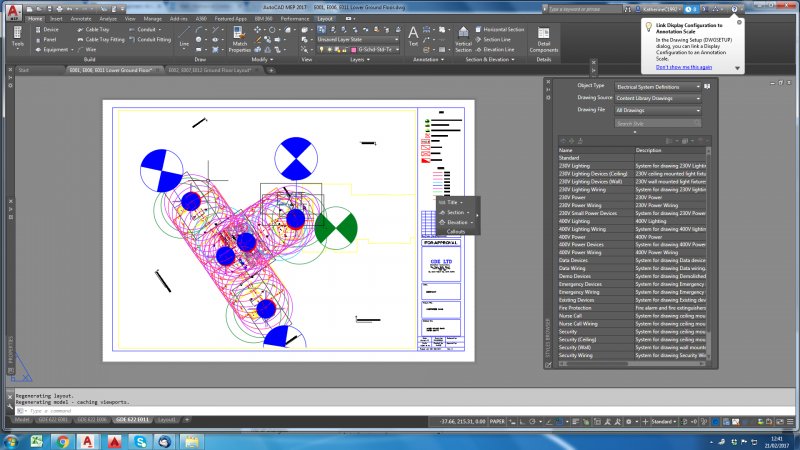
Scaling Problems!?! Model/Paper Space
katherine1992 posted a topic in AutoCAD 2D Drafting, Object Properties & Interface
Hi there, I was hoping someone cold help me I am just going through changing the scale of my drawings and for some reason the objects in my model space are now coming up huge in the paper space!? The model space is set to 1:1 I have also gone through and changed all the paper space views with viewports to 1:1 I am really not sure what is wrong I have attached some pictures to make it a little clearer. Any help would be really appreciated
-

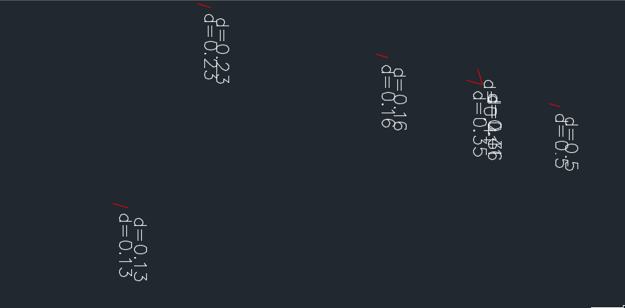
Intersections Between Lines at different Elevations
Jaru posted a topic in AutoLISP, Visual LISP & DCL
Hi There is a situation what I need is a lisp routine or vba script to find the elevations between lines or polylines at the intersection points of them to better reflect my query I post an image. I thank you in advance for the help provided. Elevation-Case.bmp -

Rotating Text around base point based on azimuth of 3D polyline
cartographer posted a topic in AutoLISP, Visual LISP & DCL
Hi guys & gals, I came across a very repetitive problem. While working with a certain type of software data is output to *.dxf as set of 3D polylines and text. From the level of software I work with, I cannot configure any text formatting details. Hence an idea to ask You few questions. 1. Is there any way of rotating text based on azimuth of a 3Dpolyline which lies within 0.3m distance from the text base? Did someone ever came across LISP of this type ? 2. is there any other (more effective) way than OVERKILL to get a rid of duplicated text ? Thank you in advance ! Regards, Adam, Geophysicist.
-
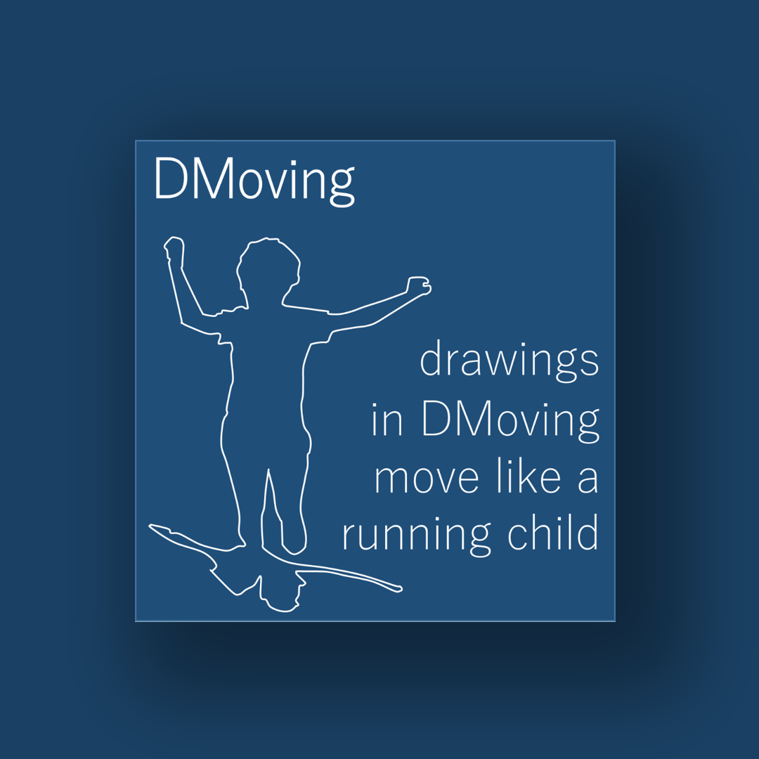
Hello everybody, I would like to inform you that in July 2019 a new concept CAD called DMoving was born. DMoving contains over 200,000 ready-made designs inside, while a burgeoning community of designers will continually enter new elements into the system. The designs will grow in number, complexity and quality with each new release of the application. An internal search engine allows to identify in a few seconds the "dynamic drawing" that comes closest to the need of the moment. Each "dynamic drawing" "moves" as if it were an integral part of a "cartoon made up of technical drawings". Special graphic elements, called sliders, allow the design to be adapted to the needs of the moment. Attention, the sliders are not simple grips, they are associated with pre-established rules, imposed by the designer who entered the drawings in the system. For example, if the slider acts on the width of a brick arch, the system will enter the number of bricks necessary to cover the width of the arch in the drawing, at the following link it is possible to see an example. https://dmoving.eu/libraries/ DMoving has a very low cost, which is why it is normally used alongside CAD or BIM already in use. We are firmly convinced that a conspicuous basis of ready-made and quickly reachable "dynamic drawings" makes the drawing process faster and helps in the design choices. Whoever uses advanced design processes such as BIM, will be able to divide the life of the project into two phases: 1 DMoving + CAD 2 BIM The DMoving + CAD phase avoids starting from the "white sheet", produces drawings in a very short time and has the purpose of making very quickly the preliminary project presentation. Once the project has started, it will be possible to switch to BIM for all the in-depth analysis of the case. We are currently strongly committed to two fronts, introduce DMoving and to expand the community of designers who can put quality content into our system. If you have specific knowledge in a specific project area and have the desire to work with us, do not hesitate to contact us. In this case we could calculate a DMoving Professional license for free. I also kindly ask you, if you have the opportunity, to spread the message. Our site is www.dmoving.eu At the link below you can download a free first version of the program https://dmoving.eu/download-request-en/ For each question, such as how we interact with AutoCAD or other CAD, or how the application generally works, please contact us. I cordially greet you and thank you very much for your attention.
-
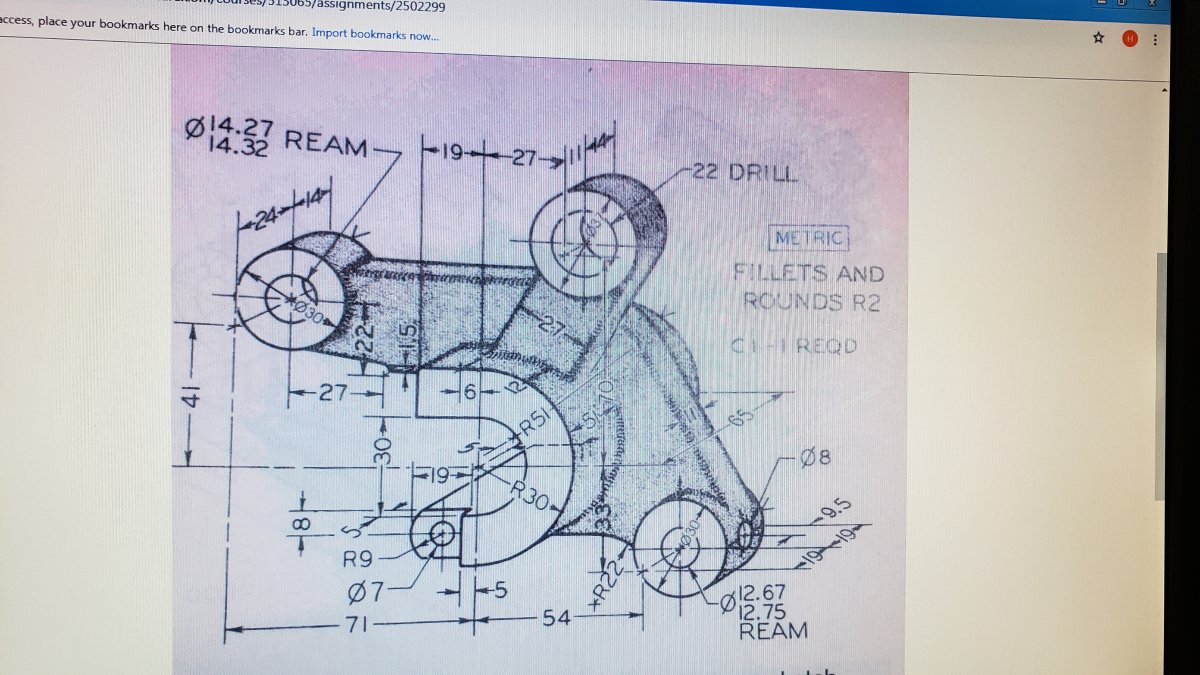
can someone create a DWG file compatible with AutoCAD 2017 showing me a multiview of this image from view top view right side view. This is for college I need it before9 am tomorrow. I cannot for the life of me pull the dimensions from the drawing I do not even know where to start. I can draw in cad just fine use all the basic tools line poly line copy mirror fillet chamfer and array ect... I just cannot make three view of this drawing if you cannot even get the first you're right you cannot pull dimensions for the other views so I can't get the first view done I can't get any of them. Complete with hidden line centerline's object lines please and thank you very much what are you doing here bud for a part for my physical in my UA make sure you all know how to go to up your tubing or something like that Santa Cruz
-
Hello, I'm looking for some help in the task of making my plans less boring. I'd like to use some non - uniform hatches to obtain something similar to the attached image. https://images.adsttc.com/media/images/595d/1743/b22e/38d8/8b00/0036/slideshow/SAN_-_siteplan_-_rooftop.jpg?1499273017 The building probably has a gradient hatch, while the lawn, and the concrete plaza, what hatch did they use for it? Thanks in advance.
-

Changing the chord of a propeller while keeping the diameter and pitch constant
melalisa96 posted a topic in AutoCAD 3D Modelling & Rendering
Hi everyone! I've an apc 8x3.8 propeller CAD file and I've to modify the chord length while maintaining the pitch and diameter but I'm not sure how to go about doing it. The airfoil used is the NACA 4412. Any ideas? Melissa -
Hello, So the following is an example of a very nice homerun. You can bend it and it'll move the arrow accordingly, reducing time spent drafting during clean up. I'd like to make one similar to the one attached that will allow you to show the wires associated with the circuit. For those not electrically inclined, Long line = neutral Short line = hot/1phase Long line+dot = ground I think it would be nice if you could bend the homerun like the one attached but also be able to change it using a dynamic block type setup where you can chose different circuit types based on what it is powering. Is anyone savy enough with AutoCAD to do something like this? Dynamic Homerun.dwg
-
I am looking to build a mini CNC mill and has been looking in CNC zone forums from long time. They have given some suggestions, but still want some machining feedback. There are so many files on the Grab cad that also didn't getting in mind. We have machinery parts or can be done from local engg shops so it is easier to get all the items except electronic parts. I just need a rough diagram to know the sizes, etc. I am looking to modify this machine to fit my needs. https://grabcad.com/library/cnc-milling-machine--3 Any suggestions to me, but it shows for wood. P.s I am looking to draw this machine in Solidworks that is the reason for posting. Shift, All the previous components were made that got help from you.
-

Extract line attributes including both handle and global width field
newtocad posted a topic in AutoLISP, Visual LISP & DCL
Hi all, I have done data extraction of my CAD file to excel using AutoCad 2017 (full version), which includes global width, but did not include the handle or any other type of ID to distinguish the lines from one another. Is there any way to get the attributes of lines, specifically global width, in an attribute table that includes the handle to distinguish the lines? If this can be accomplished in other cad software that is free besides Autocad, I'm open to that as well Thanks! -
Hi everyone. I am looking for some help / advice / tutorial links etc. I am trying to get a site layout (roads, footpaths, buildings, open space) from Auto CAD into 3DS Max. I am quite new to Max, i know how to import and scale my drawing, and i know how some of the modifier tools work, but that's about it! Does anyone know of any decent tutorials on how to turn a CAD site layout into a 3D model, using the original CAD line and without having to retrace the whole thing in Max? Many thanks Matt
-
Hello everybody, currently I'm doing an internship at an online store. My task is now to find out which data and information we should provide to our different target groups (eg architects). Since architects and regional planners especially working with CAD, it would interest me, what we can provide on our product pages (for example: http://www.badewannen.de/Badewannen/Freistehende-Badewannen/Rund-Oval-Badewanne-Rhein-180-x-80-cm-1227-freistehend.html) to simplify working with CAD. Is the drawing of a picture enough, or should we offer more downloads? And if so which ones? Many thanks Lisa
-

Planning Permission Drawing CAD book
dfooty posted a topic in AutoCAD 2D Drafting, Object Properties & Interface
Hi, I need to start drawing 2d floor plans and house plans for extensions. These need to pass planning permission so I am assuming that walls need to be a certain thickness etc. I was wondering if there are any books out there or any guides which can show me step by step how to produce a plan which can be passed by planning? Thanks, -
i trace about 40 pools a day into autocad. i use a calcomp drawing board. im wondering is there a way to put the pdf image directly into CAD so that i can just trace it directly in CAD? this would save an enormous amount of time if any one knows any way i could make something like this possible. im using cad2012