Search the Community
Showing results for tags 'arrow'.
Found 7 results
-
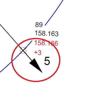
Hello, I'm new to the forum, I would like to ask you for help. I need a program / application (LISP) which will insert a deviation dart and a distance from a point to a straight line. More specifically, I would like to mark the point from the measurement and the designed line to indicate its deviation from the project. I tried to write something myself but it is too complicated for me. The arrow should show the direction in which the execution deviates from the design and it is best if its length can be determined separately depending on the drawing. In the picture I show what I mean. Thank you in advance for all your help Regards

-

dimension grip node stuck at arrow tip
rhgrafix posted a topic in AutoCAD 2D Drafting, Object Properties & Interface
I searched the universe and can't find this answer, Sometimes I find an existing dimension where one end has the node that has been collapsed to the tip of the arrow, I can't figure out how to pull it back off the arrow tip. I use 2011, any ideas? Thanks! R.L. Hamm -
I'm running Inventor 2015. I am wondering if there is a way to make custom section arrows instead of what is defaulted on the system? I have clients that have their own standards for drawings and have a custom section arrow and titles. Is there a way to make a custom one without just making a sketch or plain symbol not related to the section? I'm trying to keep the drawing intelligent...
-

Multiple drop-down arrows in one block
drafting3 posted a topic in AutoCAD 2D Drafting, Object Properties & Interface
Hi Guys, I've seen that its possible to have multiple drop-down arrows (lookup/visibility states) within 1 block. How do I do that? I am redoing my title block & would find this extremely handy for all the different options I want to select. Please let me know if you don't understand what I mean. -

FLOWLINE LINETYPE (with ARROWS)
Old Timer posted a topic in AutoCAD 2D Drafting, Object Properties & Interface
I have utilized the "old school" Flow Line Lintetype (with the ARROW that is never really centered) for many years I have been trying to acquire the preferred FlowLine Arrow Linetype (complex with the arrow shape) So far, I have not succeeded. What is the easiest way to obtain/create this preferred linetype ? (arrow directions change with the driection of the polyline).... -

Annotative Multileader Arrow Tail Placement
HeroesAndMartyrs posted a topic in AutoCAD 2D Drafting, Object Properties & Interface
This problem has been baffling me for some time now, almost 9 months and I can not for the life of me find the solution. I am using AutoCAD Civil CD 2010 and from what I've been told this problem persists on AutoCAD Architectural 2011. What my problem is when I make Annotative text with attached arrow by using the "Multileader" icon in my ribbon I get the text I desire, but the arrow tail is placed in a position that is visually displeasing. The tail attaches it self to the correct row of the text, but it stops at the length of the longest line of text. For example if my text is 4 rows tall, but row 2 is the longest length of text, it will attach itself to row 4, length 2. The two ways I've been able to achieve what I desire is to: 1. Adjust the width of the text to put the arrow tail to the text I desire. This method works, but ultimately it will make the text even more visually displeasing and thus negates itself. 2. Explode the text and position the arrow manually. This is not an option, it's too "dirty" of a method and creates too many problems. Images: This image shows how the text normally appears, exaggerated for clarity. As you can see it's two rows of text, but stops at the longest row. I want the arrow tail to be close to the word "Test". This image shows I am able to achieve the desired effect, but I've had to adjust the text box width. While this particular text doesn't look terrible, imagine if it were a 25+ word call out and the only way to clean up the text is to add hard returns and adjust the text box width. 1% of the time it works, but 99% of the time it makes the call out look so bad. This image shows what I desire (top right) and the result I get by using the method I do now (bottom right). Ultimately, I'd like the solution that allows me to make the text how I normally do and get the result of the top right text. -
Hello! I am new to these forums and have a bit of a CADMAP question those hopefully someone can answer (I tried the search and no threads came up). I know it sounds kind of amateur to ask it, but I have a mapbook that I have to create for a client and I cannot seem to find a function to get the north arrow to point at the correct position set up by the coordinate system. I know the simple answer; just manually position it, right? Well, my problem is that I have have 178 pages in my map book (its a map of Windsor, Ontario), and I was wondering if anyone had a less labouring solution to this problem? The other issue is that the client supplied the map to us showing the areas they want it divided into, and it is a bit of a mess (lets just say, nothing is squared or even referenced correctly) and I have little say in changing the map into something more workable, as it is also tied to other systems that they use for other purposes. So the question again, is there an easy way to get the north arrows in the layout drawings to point North, or do I have to do it manually?