Search the Community
Showing results for tags 'section'.
Found 17 results
-

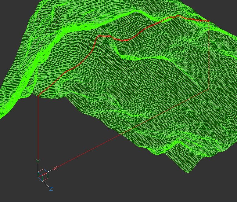
terrain Cross section of the 3D terrain
Andrej Skvarca posted a topic in AutoCAD 3D Modelling & Rendering
Hi guys, I've created an AutoLisp app which creates a cross section of the 3D terrain grid. The terrain can consists of raw AutoCAD entities: MESH / POLYFACE MESH / POLYGON MESH (one or more, even combined). As an author, I will be grateful for any comment, especially suggestions for improvements and developments. Andrej Skvarca TERRAIN_CROSS_SECTION.fas
- 12 replies
-
- 1
-

-
- mesh
- polyface mesh
- (and 10 more)
-
Hello. I was wondering if this is even possible to do with LISP. So this is what I need - I need a Lisp that would create cross section for ditch. I would like to type in existing ground and ditch marks, then existing width of the ditch and existing bottom width of the ditch. After that I would like to create a designed ditch cross section, by entering the same parameters + slope must be 1 : 1.5. (Also, both, existing and designed ditch bottom centers must align.) For background I would need frame that You can see in added file. For me all this sounds unreal, but if there is someone that can produce something like this I would be really thankful. x section.dwg
-

AutoCad (Full) 2016 section through RCP
MrButtonmush posted a topic in AutoCAD 2D Drafting, Object Properties & Interface
Hi All, I have a point cloud taken with a Drone and ported to an RCP file via Recap. Whilst I can import and crop the point cloud in AutoCAD easily enough, I simply can't make a section plan through it. I'd really like to be able to do this so I can make site plans. Online videos seem to show you picking a plan or point and getting a "plane" whilst I just get a line. I can pick it but unless I set to boundary it's just a line. If I pick this so called section I don't get the additional option in the section place panel either so !?!?!?! If I upload the RCP would anybody who's well versed in this feature see if they can do it or if the RCP is defective in some way? -
Hi all:D, I have a huge request linked to an lisp received from a friend. Lisp do next operation ... select a file type PRN (Ex 1.PRN), required datum level (ex:90) value and automatically draws longitudinal profile with data from file PRN (formatted text space delimited) . my request is ... can someone help me to do lisp advanced form of longitudinal profile as shown in attached “LGTR.dwg” file(in green rectangle). When I upload file 2.prn in lisp drawing the result from the green box. I would appreciate if someone can suggest an idea or if modify the Lisp as showing the longitudinal profile in green border. to use prn file please del .txt lisp command is LGTR datum level for my files is 90 Thank you for your time. LGTR.dwg LGTR.LSP 1.prn.txt 2.prn.txt
-
Hi I have a model with 3D walls, slabs, stairs ect. (AEC-objects). In that drawing I allso have an x-ref with some walls and solids and surfaces. When making a Vertical Section and enable Live Section, it only cuts through the objects in the main drawing - not the x-ref. How do I make it cut through the objects in the x-ref as well? Please help
-
I'm running Inventor 2015. I am wondering if there is a way to make custom section arrows instead of what is defaulted on the system? I have clients that have their own standards for drawings and have a custom section arrow and titles. Is there a way to make a custom one without just making a sketch or plain symbol not related to the section? I'm trying to keep the drawing intelligent...
-
Hello, At the request of a co-worker I am trying to generate a table with the station number and % grade of the lane subassembly at that station. Any help is appreciated. Additionally, they want it to be a live, dynamic table in the drawing, not a toolbox report dropped into excel. Thanks! Phil
-
Hi again. Is this possible at all? I want to add a headwall / retaining wall at the left side as shown for this section only.
-
Here's an odd one (hi everyone!), a planning consultant has asked me to show the roof pitches on a site plan, and I'm stumped. Any ideas? This is what I've done so far: Sorry to bother, any suggestions welcome! I'm so far thinking of showing a few basic cross sections on the same drawing sheet. This isn't a CAD technical thing, just a 'how to portray information' thing Look forward to your comments
-
My workplace is 50/50 SW/ACAD and we are looking at how to make our output from both look as similar as possible. Does anyone know if you can somehow replace the standard section lines in solidworks? Something that looks like this instead of one of the two options within solidworks would be great: http://imgur.com/RhYRtiF I could right click then "Hide section line" and then manually put a block in its place but it would be good if the Letter in the block was linked to the view that was created by the hidden section line?? Wouldnt even mind if the reference text (yellow in the image) was an attribute and not linked.
-

Section, 3Dclip, Camera, Transparancy
ErwinMeulman posted a topic in AutoCAD 3D Modelling & Rendering
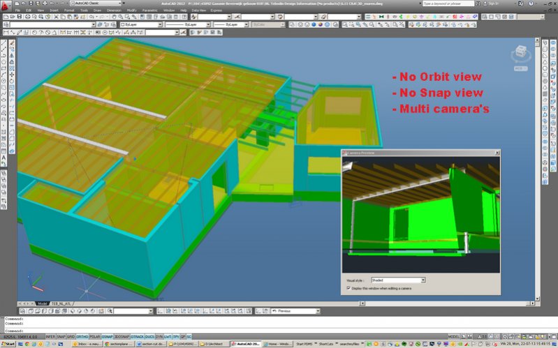
Can somebody tell me what the best options is for a section in AutoCAD. I toggle with xref, layers on/off (edit xref in please) to get a clear work area. But mostly all xref and layers must be switch on to snap/model parts. So I look for some options: Camera options (not what I expect, I can work in this view, multi-camera's is good) Livesection (only possible for solids and not for meshes, it's slowing down you system) 3Dclip (you can't same multiple sections, it's not what I expect) So can somebody tell me what to use, maybe something like sketchup)
-

3D Sectional Drawing Views in Autocad 2014
nicolas posted a topic in AutoCAD 3D Modelling & Rendering
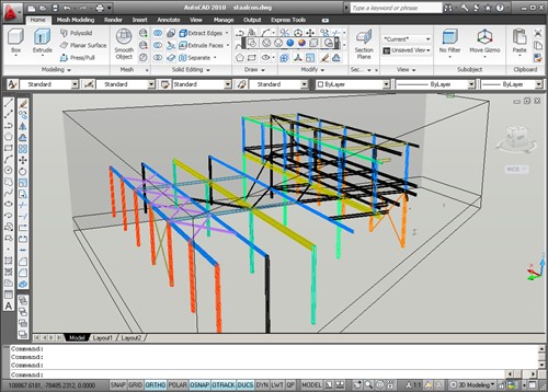
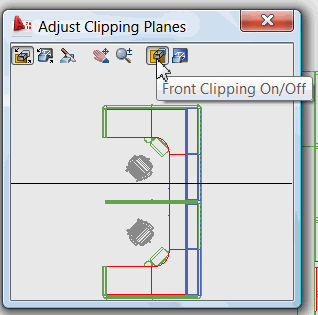
Hi, I need help on 1. clipping 3D Drawing views and 2. chaging the hatch pattern/scale in the sectional Drawing views that the generated automatically when hatch option is on. A last question is whether Sectional Drawing view is better than a section generated with section plane. Thanks. -
I am using autocad mechanical 2012 and it's the 1st time i know sectionplane icon. But when i click sectionplane, autocad response like this : Command: _sectionplane Unknown command "SECTIONPLANE". Press F1 for help. anyone help me please. .
-
Does anyone know how to add the profile elevation to the section view band style? I have a case where the profile is theoretical because it is under a median for the majority of the project. Because of this, I have my assemblies 4” above the profile grade line. I would like the sections to show the existing elevation (easy enough) and the profile elevation, not the section elevation. Any suggestions? Thanks. Quick update for anyone else with this issue: For a temporary answer, I made a second corridor without an offset in the assembly and sampled it in the section view, but did not draw them, then used that section elevation.
-
Hello, I made an irregular solid object using the LOFT command and a few splines as sections. The object is approximately 200 units long and I need to get sections from it (polylines or regions) every unit. Is there any LISP that can do this? Thank you
-
Is there a way, when sectioning model consisting of several solids, to output them with various hatches as intersection fill. I'm currently using the section plane (under the solids ribbon), but all solids end out with the same hatch. Only customizing option i can find is color byLayer.. Is there a way to link the hatch pattern to fx. layer? So that an object on one layer comes out with, say, solid hatch, while another on another layer comes out with another hatch pattern? It is fairly simple modeling, so it would overcomplicate the project, i think, to go towards aec-objects. our projects normaly consists of a concrete floor, though fairly complex in geometry, and various ground-fill layers underneath. Any suggestions? In advance
-
I am having an issue with saving a drawing as an AutoCAD file. The drawing involves an assembly with which I have created several section views, using the 'include slice' and 'slice all parts' options for each view. I have then rotated some of these views as that allows me to rearrange the sections on the drawing sheet independent of the main part. The problem I get is when I save a copy of this drawing file as a .dwg, only the main part appears in AutoCAD. There are no section views included. Is this something that happens with the 'slice' feature on the section views? I am using Inventor 2009 and trying to open with AutoCAD 2010, so maybe that is an issue also?