Search the Community
Showing results for tags 'bevel'.
Found 3 results
-

Dynamic Block - Rotate/Stretch along a linear path.
dblclkmatt posted a topic in AutoCAD Drawing Management & Output
Hello CADtutor, First time post, long time reader. Huge fan. I tried to find this problem on the forum before posting, but had no luck. I am trying to have a dynamic block that will show the profile of a steel plate, detailing the angle of a bevel. Including the plate thickness, the land, gap and the actual angle of the bevel. I've gotten most of it figured out, but having a grip to SET the angle at a specific number, while maintaining the drawing's integrity is proving difficult. I have attached the block I have created so far (minus the previous attempts to rotate the beveled angle). BVL_detail.dwg The basepoint of the rotate parameter should be at the junction of the bevel & land. I need it to stay connected to the end point of the top-most flat line as it rotates, which means the lines need to stretch to match the changing angle. It will either rotate that line along with it, or if I apply a stretch tool, it gets all disconnected and just plain wrong. One of the things I am liking about my current set up is I can grab a grip, and then type the number I need and it will pop on into place. Was hoping for the same effect if I typed in the angle, it would be exactly that, while also adjusting the drawing. I'm hoping to get some direction of things to try, or a straight solution. I've been tweaking with it for the better part of the day and finally conceded to ask for help. Even alternate solutions would be greatly appreciated. My first attempt was to have prompts that ask me for the details, and after I answered them all, it would just makes the detail for me. But that's some super secret CAD magic I just don't possess yet. If clarification is needed at all, please let me know. Thanks in advance! -
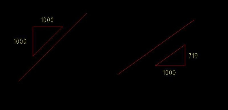
Hi guys, hopefully a pretty simply one here. I was just wondering if anyone has a routine (or knows of one) which will create a 'bevel' symbol/dimension similiar to the one shown in the attached image? Im not certain that im using the correct terminology to describe the dimension type - and i have tried a bit of googling with little luck (not knowing exactly how to describe what i was looking for). So... does anyone know of a routine which would create such a symbol? or of there is another method i can use? Thanks so much for any help.

-
Hi, I'm having trouble visualizing how to constrain two basic bevel gears to have them rotate in tandem. I'm using Inventor 2011 Pro and I'm not sure what the exact steps are. Thanks!