Search the Community
Showing results for tags 'electical'.
Found 6 results
-

How to use Wire Copy (AECOPYWIRENO / WD_COPY_WN) in LISP
NicholasCAD posted a topic in AutoLISP, Visual LISP & DCL
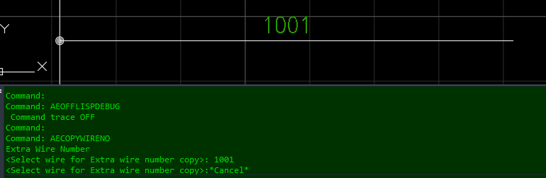
(Hopefully this Question has not been asked. The Search gave no Results.) For Context: I have created a Program that generates a complex Component (Block, Wiring, Text) onto a Sheet. The Program uses .LSP and .DCL for ease of Use for our Operators. The Prompt has Options to configure the Component to any Options we need. Inquiry: I need to update the Program to include Wire Numbers and Wire Number Copies. (I will be trying to use "WD_PUTWNXY" Command for New Wire Networks, although I have yet to do so.) For Wire Number Copies, I was hoping to use either the "AECOPYWIRENO" or "WD_COPY_WN" Commands. The Problem with these Commands is that they do not allow for Coordinate Placement. When running either Command, the Command Line is requesting to select a Wire as an Entity. What I would like, is an example of a LISP that completes this Task using a Coordinate System to select and place the Wire Number Copies. Any Advice would be much appreciated!
-
I am attempting to create a Dynamic Block for electrical home runs that behaves similarly to home runs in Revit. Essentially it is a Spline with (3) Control Vertices and an Arrowhead at opposite end from the Basepoint. I have created the Dynamic block to include the desired visible elements and I've gotten the Spline to behave correctly using Stretch Actions. The only problem I am having is that I can't get the Arrowhead to follow the end of the Spline correctly. I would like it to "bend around" with the Spline but it wants to stay at a fixed angle. If anyone can point me in the right direction (pun intended) or modify the attached example of my Dynamic Block, that would be appreciated. Also, I am aware there is an Mleader Style that utilizes a Spline instead of a straight line. However, the Spline is based on Fit Points instead of Control Vertices and simply does not behave the way we need it to, thus the reason for the Dynamic Block. HOME-RUN.dwg
-
I am attempting to create a Dynamic Block for electrical home runs that behaves similarly to the home runs my company uses in Revit. Essentially it is a Spline with (3) Control Vertices and an Arrowhead at opposite end from the Basepoint. I have created the Dynamic block to include the desired visible elements and I've gotten the Spline to behave correctly using Stretch Actions. The only problem I am having is that I can't get the Arrowhead to follow the end of the Spline correctly. I would like it to "bend around" with the Spline but it wants to stay at a fixed angle. If anyone can point me in the right direction (pun intended) or modify the attached example of my Dynamic Block, that would be appreciated. Also, I am aware there is an Mleader Style that utilizes a Spline instead of a straight line. However, the Spline is based on Fit Points instead of Control Vertices and simply does not behave the way we need it to, thus the reason for the Dynamic Block. Thanks! HOME-RUN.dwg
-

Excel Data linking; Table wrapping text format issues
DataLinkQ posted a topic in AutoCAD 2D Drafting, Object Properties & Interface
Hi everyone, Setup; OS: Win 7 Pro X64 Product: AutoCAD 2015 Electrical CPU: i7 Graphics: AMD FirePro M6100 FireGL V Ram: 16GB Problem; I've created a datalink table to an Excel spreadsheet, and I'm only having issues with tables that required a break (table wrapping). Once I break the table and setup text properties; text height, alignment, headers, cell widths. Everything looks okay until I close and open the drawing. The first half of the table remembers the settings, but the second half always reverts back to .5 text height and top center alignment (headers and cell width are still in place on the 2nd part of the table) Solutions I've tried; I've tried to do the formatting before I break the table, I've tried after its broken. I right clicked on the tables and "Remove All Property Overrides" which makes the text all crazy, so I setup text properties, qsave and close. once I open the drawing text height and alignment changes again. If I try to "Remove All Property Overrides" the text doesn't change, so I think that function worked correctly. Summary; How can I get the 2nd half of the datalinked table to remember all property settings? I'm out of ideas Does anyone have some other solutions to try? Thanks for your time. -DataLinkQ -
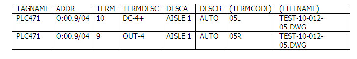
I have a fully electrical drawing set complete with I/O from my PLC I want to generate a .xlm file. I then want to write a program that will scrape the file looking for I/O addresses, and then assign aliases based on the descriptions. I’m having trouble with the .xlm file. When I generate the file the I/O looks like this: - Wire> What I need is something that includes the description. I know they are associated in some way because if I export to Excel the same I/O point looks like this: What do I need to change in order to associate the description to appear in my .xlm?
-
I just typed this whole thing up and my explorer crashed….. Here it goes, short version this time. First off, I would like to thank everyone on here for sharring information and providing help to those in need, it really does make a difference, so thank you. I work for a small drafting company and wespecialize in BIM coordination. I amusing MEP 2012 and love it for coordination with other trades. Most of my work is electrical. One of the companies we work for is going tostart a Pre-Fab division and wants us to create all of their Pre-Fab drawingsafter the work is coordinated. Last weekwe went to a meeting on TSI’s CADElect/CADPipe, and almost everything theprogram has to offer can be done in MEP. I prefer the level of customization available with MEP vs theCADElect. However, the one thing thatdid stand out was the couplings in CADElect. You can select a cut length for a conduit in both programs, but in MEPit will simply divide a conduit up into the specified length and in CADElect itwill place a coupling between them. Isthere a way to get these couplings to be automatically added in MEP? I searched the Google Machine and came upempty handed. Any input on this matteris greatly appreciated. I don’t want toleave the MEP, but I might have to….