Search the Community
Showing results for tags 'subtract'.
Found 9 results
-
Hi I have a problem. If you can help I'll be glad to you. I have some chainage labels as 1+234.56 format. I want a lisp for increase-decrease selected chainage values by specified amount. Thank You
-
 Hi All, I have a solid model (layer "base solid" ), from which i want to subtract (layer "Subtract solid" ) and union (layer "Union solid" ) to the base. I get Boolean subtract and union error "Modeling Operation Error:Wire being deleted crosses face boundary." I have tried many different ways of modelling and i arrive at the same error. Here is my file: https://onedrive.live.com/redir?resid=E78CC5E0964AAF6B!147&authkey=!AIrqRWOhdHnKp20&ithint=file%2cdwg
 -

Unable to put any more holes in solid.
AerospaceDesk posted a topic in AutoCAD 3D Modelling & Rendering
Here I have a flanged Alclad Plate I developed in AutoCAD2015 Trial, I since ran it through CorelCAD 2015 because I ran out of trial time. I have to sort it out to get more time. The problem is that I tried to put a third flange on the plate (a 90 deg one) after I had successfully extruded all the holes you can see. The 3rd flange was created by extruding concentric cylinders and subtracting a rectangular block from that. I found out I was having trouble when I tried to put a relief hole in the corner where the end of the 3rd flange meets the plate at a perpendicular intersection. That did not work; but sheetmetal workers do this before they bend the metal. I found that in the 2D views, the third flange separates form the plate. In the 3D model space, AutoCAD and CorelCAD both report the "assembly" as a 3D Solid. I would like to learn what is causing this to happen; stopping me making more holes.. Thank you for your help. CorelCad Alclad Flange 02042015 Stiffening Flanges A Relief Hole.dwg -
Alright so I have to subtract that little box inside the guide block so it looks like this http://gyazo.com/bc7fdf0552af580344d665e45127b2db I have no idea how to do this.. Thanks:? exploded version guideblock.dwg
-

subtract command not working like expected after import
jcc5018 posted a topic in AutoCAD 3D Modelling & Rendering
Hey guys, I am working on a project where I am attempting to design a pendant. I wanted to do this in solidworks but I am not as experience with that and I'm having issues, so I went to what I know, AutoCAD. Unfortunately I am still having problems and I think it has to do with the import file from Adobe illustrator. What I have is a circle with different parts and block text that I would like to cut out. I saved the illustrator file to a dwg file and it imported with a hatch over all the solid areas. I deleted that to get the respective outlines, and extruded. Most loops extruded but some failed to do so for some reason. But I have an option to convert to a pline, but then I get a specify precision dialog which adds a bunch of points along what seems to be a straight line. Anyway, when I do manage to get things extruded, and go to perform the subtract command (or intersect which would be faster) I click the main shape, and then click the items I would like to remove, but it doesnt do anything. I have no idea what the problem is. Does anyone have experience with this? I did get one whole to subtract, but I really dont know the difference between that and the others that made it work. (P.S. If anyone has experience with solid works, I imagine this would be the same process. But I can get the outlines to appear, and extrude the outside shape, but I can't figure out how to get the inner holes to cut out.) Unashamed2.dwg -
How can I make this allow me to select the text to be edited? (defun c:AFF ( / ss) (vl-load-com) (if (and (setq ss (ssget "X" (list (cons 0 "*text")))) (setq amt (getreal "\nPlease type the amount you would like to add: "))) (progn (mapcar '(lambda (z) (vla-put-textstring z (rtos (+ (atof (vla-get-textstring z)) amt) 2 2))) (mapcar 'vlax-ename->vla-object (vl-remove-if 'listp (mapcar 'cadr (ssnamex ss))))) ) ) (princ) )
-
The subtract region operation is something i have already done, but what i'm having trouble with is determining when a region is inside another one. Here I attach a sample file: cadtutor forum.dwg The main task is checking regions one by one, then determining whether it as or not another region inside. If it does, subtract the interior one. I don't know how to check if one contains another inside. Help!!
-

Subtracting Lofted Surface using Extruded Surface - Doesn't Work
dulerong posted a topic in AutoCAD 3D Modelling & Rendering
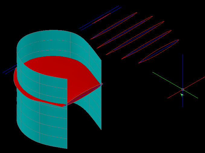
Hi all, Problem: Green Surface = Extruded Surface Red Surface = Lofted Surface I'm trying to subtract the green surface from the red surface. Commands Tried: - Subtract - Surftrim So far these two didn't work out very well. "Subtract" didn't do anything at all, while "Surftrim" helped me to get rid of anything outside of the cutting surface. But the problem: After Surftrim, the lofted surface's inside shows out, and I found out that it's not solid/filled inside, but rather it's a hollow space inside the lofted surface. I'm trying to create a fan blade, and using that green surface as a shape-maker. Anyone has any idea? P.S. The original post and picture owner is in this link http://www.cadtutor.net/forum/showthread.php?47775-How-to-draw-table-fan-blade
-
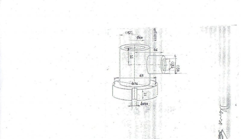
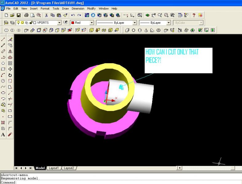
I have a piece to make in autocad 2002 and my work was blocked by a command i dont remember. I am stuck here,how can i cut only that part of the piece? With SUBTRACT doesnt work. i attached the original draw i have to make too. Please help me,if you're so kind fff.dwg