Search the Community
Showing results for tags 'problem'.
-
Hello, I would appreciate advice on the implementation of a process that matches one region of autocad (corners of a entity) into an empty subsection of a larger region. I have attached a drawing that presents the problem that I wish to solve. playground.dwg
-
Hello i have some problem with intersect point. I will upload dwg file. I dont know why when i try to get all intersect point from the red something go very wrong. I need all intersect point from the red lines. Thank you Try_5.dwg
-
Hello, i have problem with creating region. In my case i try to create grid region i have 4 polygons and when i select all lines from 3 of them it work perfect but when i try in last polygon something go wrong. Upload file. Thank you and Happy Holidays. TRYYY_XX.dwg
-

How to calculate road widths between a given distance?
vorno posted a topic in AutoLISP, Visual LISP & DCL
Hi everyone, Long-time user of the forum, but first-time poster. Thank you all over the years for your various contributions, they have helped me a lot over the last ~8years! My problem: I have ~15km of road where I need to calculate the width of the existing road every 10m, using a survey consisting of polylines. I then need to take this information and put it into a table (Excel for example). So far I've found a lisp routine that creates dimensions between two objects at a given interval, but I don't know how to get the information into Excel. Furthermore, it would be highly beneficial for me to identify the location of the measurements in Excel (whether identified by a simple sequential number or by x/y data). I look forward to this discussion! Thank you in advance, Vaughan. -
I have a problem with trim command. When im in the trim command, window selection doesn't work. Only crossing window. I've been trying everything that i can like PICKFIRST, PICKDRAG etc. I searched it online but there is no solution. :(
-
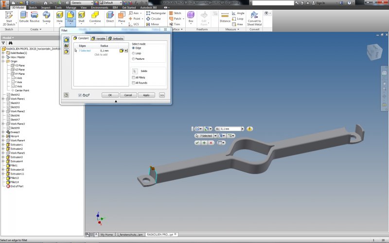
Hello people! I have problem with fillet as you can see it on picture. Can't figure problem out. Do you have any idea why this is happening, since this is tenth (similar) part i have done. File is over 500KB so i can't upload it. Thank you!

-
Dear All, I am new to the forum so thanks in advance. My problem is this I have been asked to create an artistic cube drawing which is 1 metre square, then I have to insert 100 separate holes right through all 3 (6) faces, there is 100 holes in all starting at 1mm then 2mm, 3mm... and so on through to 100mm. Would there be a formula for this does anyone know? Really appreciate any input on this nutty problem. Campaigner
-
Hello I hope you can help me. I am trying to draw a cover from a technical drawing. I have tried several approaches but I have yet to be succesful. Do you have any ideas how to draw this? I think some information may be lacking?
-

Problem changing display colour of xref polylines..
astitchintimesaves9 posted a topic in AutoCAD Drawing Management & Output
I need to produce a pdf in black/white/red. To achieve this I'm using a colour ctb but changing all the viewport layer display colours to white (except the linework that I need in red) and therefore print black. The problem linework is xref and seems to be either circles, rectangle or 3D polylines, that will not change their viewport display colour even though I have actually changed them to white? They just print their original colour. -
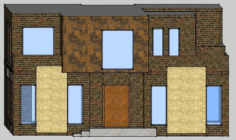
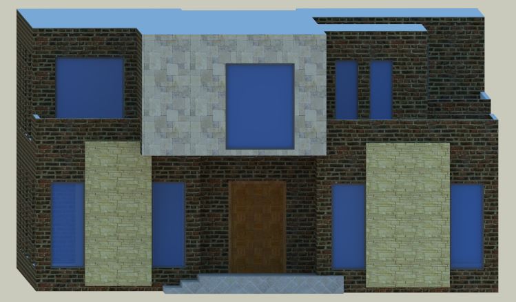
hey guys i'm new with sketchup rendering. i changed the tile color and apply on wall but when i rendered it using vray... it showed me the original color of tile not the modified color. any help to fix this will be appreciated. thanks in advance!! :)sketchup you can see that 1st image is my model and 2nd image is rendered.. and the color of wall is different.
-

Intersting Viewport/layer phnomena
Dinochrome posted a topic in AutoCAD Bugs, Error Messages & Quirks
I have a layer that seems to displaying incorrectly. I am trying to freeze "NoPlot" through a viewport. It is also freezing out on paperspace. Am I wrong in thinking it should only freeze "inside" the viewport? Test.dwg -

Problem: Dynamic Block with Rotation Action
JackStone posted a topic in AutoCAD Drawing Management & Output
Good evening. After some extensive reasearch I could not find a way to solve my problem, so I have come here hoping you guys can save me yet again. I've spent the past three days trying to create this block and at the moment I'm quite frustrated. I'm trying to create a dynamic block with multiple actions. I need a flip, a stretch, a visibility and a rotation parameter and a basepoint. Everything works just fine until I add the rotation action. I need certain entities to rotate but the text to remain at 0 degrees. I learned that you can do that by assigning point parameter to move the text and then include only the point parameter in the rotate action selection set. The problem happens when I try to do that and also add a basepoint. With the basepoint the behaviour of the attributes (or text entities) becomes erratic. Sometimes they even spin in an opposite direction when compared to the other entities. I don't know why that is happening. If I do not include a basepoint explicitly AutoCAD automatically creates a grip that works as a basepoint. In this case the rotation of the attributes and the other entities works just fine, but the new basepoint grip is left behind when I use the rotate action. I have attached a file containing three slightly different blocks. The first one is without any tinkering; on the second one I made the rotation action "Independent" (sometimes that helps, but it didn't work here); on the third one I deleted the explicit basepoint and you will notice the behaviour I described above. I thank you all in advance for your time and expertise. FlagBlocks.dwg -
Using the Page Setup Manager I set a page size of A1 landscape. When I scale my model in Model space to 1:20 (a small bathroom drawn metric 2m wide) it appears about 4 times too big. What could I be doing wrong. The units in model space is metric. It was initially working but somehow I must have reset something. Any thoughts really appreciated.
-
Hello everyone - been a long time since I was on here I've created a solid model using Autocad 2014 which has multiple solid entities that I want to export to Revit 2014 as individual entities. When I import it into Revit 2014 however the drawing comes in as a single item, and if I right click the bounding box and try to either partial or full explode it, it completely disappears. Is there any way of getting the entities changed from Autocad to Revit so I can add BIM information to each separate entity within Revit? Thanks in advance for any advice and a big "Hello" to anyone that remembers me Spacepig
-
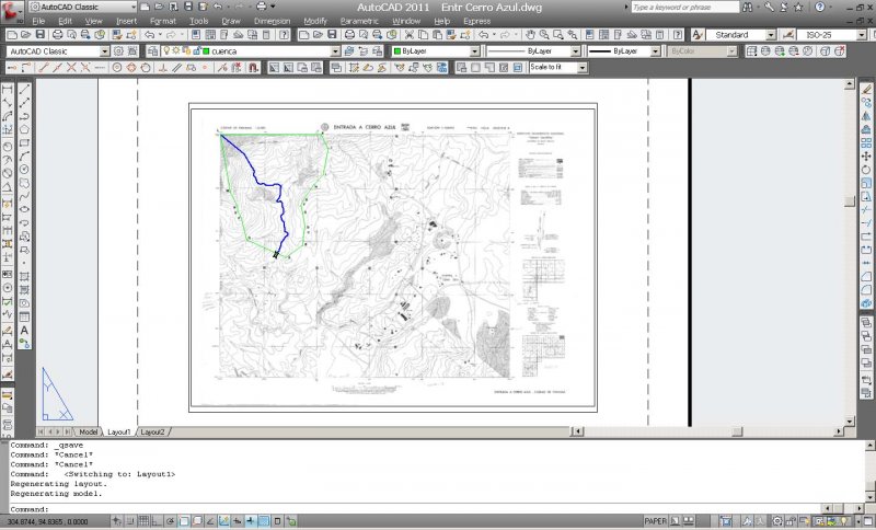
Hello Everyone. I'm drawing polylines within a chart of elevation contour lines of a mountainous region in my country. This is for the design of the drainage hydraulics of highways. The Contour Chart which is in jpg format, I have saved it in photoshop in medium size to help make my autocad drawing the less heavier in size. In fact, my AutoCAD dwg file is only 69 KB big. I have however georeferenced my Chart by UTM coordinates, so it is a little bit big in the drawing. My drawing is in milimetres and the chart size is: 3861 x 2848. Here is the layout view of my drawing: What is making my AutoCAD crash all the time when I regenerate the model? Is there anything I can do to stop this from happening? I try to save my drawing all the time though, and whenever my AutoCAD crashes I have to close it up, then I have to open AutoCAD and the drawing again; but this is a bit tedious.
-
Hello everyone, I'm writing because I need to disable the dynamic input in AutoCAD. It's irritating to me, because I'm more used to a much older version of AutoCAD. I just found this forum while searching through the internet and this is my first post here. Upon searching through the internet I found a thread here that says that I have to set DYNMODE to "0" to turn off the dynamic input. Alas, I have no clue as to at which subfolder of the registry this variable should be. Could anyone help please? Thank you all for your time.
-

Quick properties dialog box
jdavid10 posted a topic in AutoCAD 2D Drafting, Object Properties & Interface
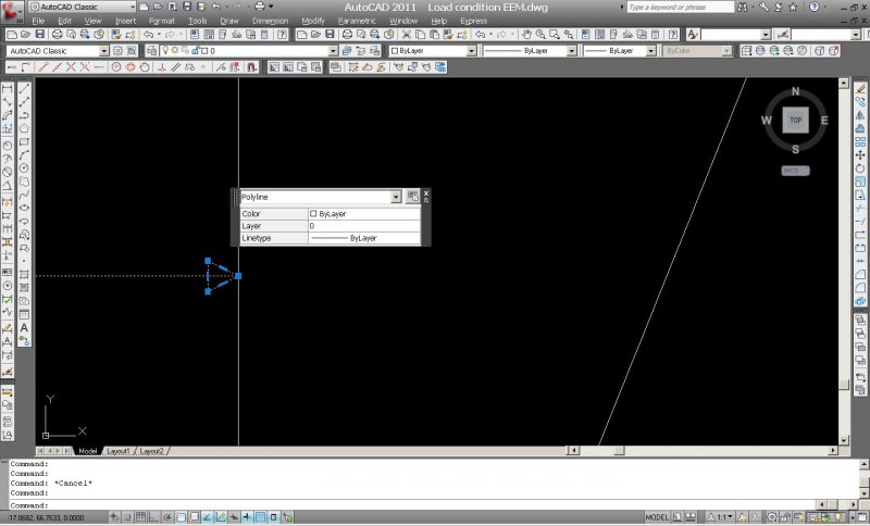
As I draw, whenever I click on an object (e.g. a polyline) a small dialog box appears right next to it. For example: in the drawing below I'm selecting my own polyline which I've made into a line with an arrow tip. Now I select it because I want to change something but the small dialog box appears at the right. If I close the dialog box and click on another object, it shows back up again for whichever new object I'm selecting. This is quite annoying. How can I disable this? Thank you all for your time reading my inquiry. Please help.
-

mtext background masking not working over xrefs
rhgrafix posted a topic in AutoCAD Bugs, Error Messages & Quirks
I have a dwg that I'm using paperspace for text with a viewport of an xref'd 3D model, I have some mtext with background masking, using drawing background color, border offset factor of 1.2, it only masks when I hover over the text. I used Draworder and brought the mtext to the front, nothing I do works, what can the problem be? Fill is on, shademode is 2Dwireframe. I am using Acad 2011. Thanks for any help! R. L. Hamm -
Hello, I downloaded student version of "Autodesk 3DS MAX 2013". I would like to install the Apex/PhysX plug-in but I can't. When I try to run the Apex plug-in, Autodesk write "Apex plug-in is not made for this version of the program". So, I would like to know if Apex/PhyX is available for student version of Autodesk and which manipulations have I to do. Bye, Samuel.
-
Hi, everybody I just want to ask how to make my drawing as region that cover the close area. When i select the circle object and tooth object, it not become a region . I already connect all the line but its not working.Hope that everybody in here can help. 9_8 autocad kecikkkan tooth.dwg
-

Can you export cross section lines from hec ras to autocad??
aaroncourtice posted a topic in AutoCAD 3D Modelling & Rendering
I need the actual cross section LINES that are shown in the HECRAS model, not just the alignment... I've tried check marking everything that the "GIS export" option in HECRAS gives you to no avail (all I can get into ACAD is the alignment, not the 74 cross section lines along with it)... HELP!!!! -
Hi All, I am having a problem with AutoCAD 2011. Here's the problem step by step: 1. Select a line 2. Right click and select polyline 3. Select width Here's where the problem arises. ACAD used to prompt for a width now it runs the PEDIT command and asks me to select a line and then gives the usual pedit commands via the command line. Not sure what has happened here but would appreciate any advice on how to reset this.
-

Problem with code to select a single piece of text using ssget.
Reu posted a topic in AutoLISP, Visual LISP & DCL
What is wrong with my coding? (defun 1ststring () (if (while (= str nil) (setq ss (ssget ":S" '((0 . "TEXT"))) str (cdr (assoc 1 entget ss)) ) ;_end setq (setq str nil) ) ;_end while ) ;_end if ) ;_end defun -
Hi, I'm on AutoCAD 2012 student version, Penn Foster Civil Drafting Plate 2, and I keep getting an error message "Cannot fillet between these two entities". I'm trying to fillet between a circle and a line (west quadrant). The circle radius is 25 and the fillet radius is 20. My main concern is that I am quite certain I have drawn all the entities correctly, and if I can't fillet this, I can't proceed with the rest of my drawing. It's for a cul-de-sac at the end of a driveway.
-
When exporting to an IGES format the threads are missing. Why? Thanks, Victor