

Map Modifying
Introduction
Map modification takes place in one of two places: either on the Modify Panel with the use of one of two modifiers, or in the Material Editor as part of the material parameters. Although the coordinates and scaling of a material can be changed in the material itself (scaling being efficiently handled by using 'real-world mapping' parameters for walls and paving), most modificatons in the Material Editor relate to various added effects such as 'noise', 'bump', reflection and colour enhancements etc. The placement and orientation of materials on objects is usually handled by applying one of two map modifiers
This tutorial describes the use of the UVW Map Modifier, the Map Scaler Modifier and the most useful parameters in the Material Editor
Before starting, however, it is important to recognise a difference in the default settings for mapping materials between MAX and VIZ. VIZ has 'real-world mapping' settings defaulted to On in the Material Editor and in the UVW Map Modifier. MAX defaults are set to basic mapping settings as are shown in this tutorial
Real-World Mapping (defaulted to On in VIZ)
Real-world mapping is an alternative mapping technique in Autodesk VIZ that is on by default. The idea behind real-world mapping is to simplify the correct scaling of texture-materials applied to geometry in the scene. This feature lets you create a material and specify the actual width and height of a paving texture, for example, in the Material Editor. When you assign that material to an object in the scene, the texture appears in the scene with correct scaling
NOTE: Key Fundamentals takes you through the basic mapping parameters that are the default of MAX. This is to give a more rounded view of mapping materials and help you understand all the mapping parameters. To explore the advantages of real-world mapping consult the MAX/VIZ help system once you are adept at basic mapping of materials
Procedure to convert from real-world mapping to basic mapping (for information)
When resetting a scene in VIZ you will be have settings in the Material Editor and UVW Map Modifier that are configured for real-world mapping. To convert real-world settings to basic settings when required do the following:
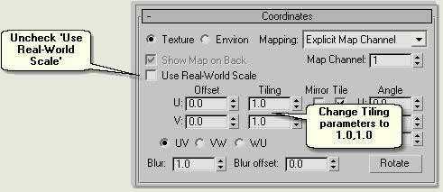
- When a map is assigned to a material uncheck Use Real-World Scale on the Coordinates rollout and change the Tiling to 1.0 ,1.0
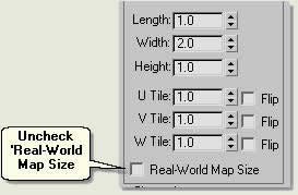
- Similarly, when applying a UVW Map Modifier to an object uncheck Real-World Map Size
NOTE: Although this sounds complicated it will make more sense once you are adept at basic mapping techniques. Also, all the materials in the tutorial files are configured for basic mapping parameters, so you do not have to pay too much attention to this issue presently
Download Sample Data
kf405_files.zip (38kb)
module_4_maps.zip (5.2mb)
UVW Map Modifier
To explore the UVW Map Modifier you will use a Brick procedural mapped material which can be assigned to different types of geometry
TIP: On the Right Click Viewport Menu check Texture Correction to view textures (images) correctly in the viewport. If this is not checked everytime you open the scene then paving and wall tiled textures can look distorted in the viewports. However, they will render correctly
- Open kf405_01.max
- Select Box01
- Open the Material Editor, select the Bricks material in the sample windows and Assign Material to Selection
- Modify Panel > Modifier List > UVW Map modifier
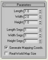
- Uncheck Parameters > Mapping > Real-World Mapsize
This applies a UVW Map Modifier to the box and enables the use of a number of parameters:
Parameters rollout
- Change the Mapping to Box. The default is Planar, so to map the sides of the box correctly this needs to be changed
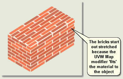
- Notice that the bricks are stretched because the material has been assigned and 'fit' to the box by default. Notice that the Height, Length and Width spinners show the dimensions of the box and that the Tiling parameters start at 1,1,1. Also notice that Real-World Map Size is checked Off - this is defaulted to On in VIZ (not MAX)
NOTE: UVW equates to XYZ for geometry coordinates. UVW is the same, only for images
- Change the Width spinner to 1. This puts the dimensions and aspect ratio of the map back to the correct proportions
- Change the U Tile and V Tile to 1.1 each to make approxiamately 9 bricks span the box height. This would be the real-world proportions of a brick wall at 1 metre high
The top course of bricks, however are not a full brick:
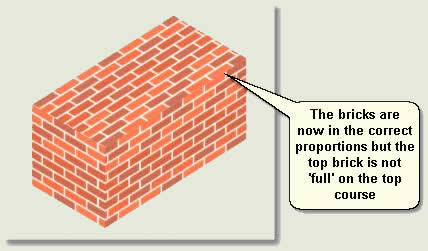
To correct this you need to position the correctly tiled material on the box
- Modify Panel > UVW Map > Sub Object > Gizmo
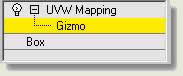
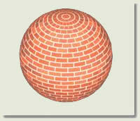
- In the viewport move the gizmo along the X, Y and Z axes to position the bricks correctly at the top and sides of the wall
- When finished select Gizmo (coloured yellow to show it is active) again to exit out of the Gizmo sub-object
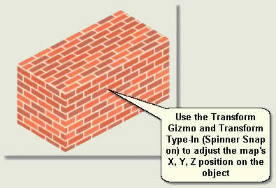
- Select Sphere01. Keep the Material Editor open (this is a modal dialog)
- Assign the Bricks material to the sphere
- Modify Panel > Modifier List > UVW Map modifier
- Change the Tiling settings to achieve the desired result - bricks would not be constructed into a sphere. This is for illustration purposes only
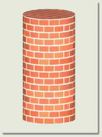
- Repeat the process for the cylinder, this time using Cylindrical mapping
- Check Cap next to the Cylindrical mapping radio button to cap the map on the cylinder
- Repeat the process for the plane object, this time keeping the default planar mapping
- Modify Panel > UVW Map > Sub Object > Gizmo
- Rotate the gizmo to rotate the brick material on the plane and move into position
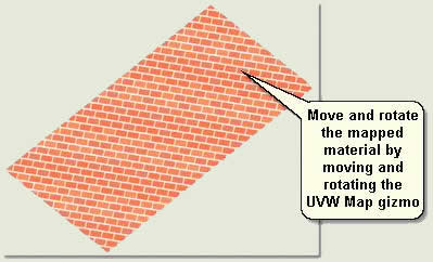
- Again, when finished, make sure you exit out of the Gizmo sub-object by selecting Gizmo
MapScaler Modifier
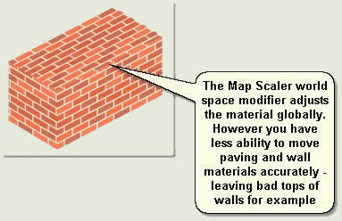
The MapScaler modifier is a World Space modifier. This means that it is carried with the object to which it is assigned, but uses world space rather than the object for its effects. World space modifiers are convenient for modifying a single object or selection set
- Open kf305_01.max again
- Select Box01 and Plane01
- Modify Panel > Modifier List > MapScaler modifier
- Adjust the Scale to below 1 and move this up and down. As you can see this is fairly arbitrary, yet quick
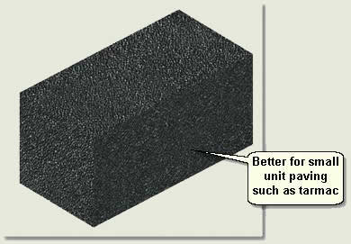
The MapScaler modifier is good for quick, less geometrically accurate results and for any small unit paving and wall materials such as tarmac, concrete, sand. gravel, grass etc
- Assign the Tarmac material to the box and use the MapScaler modifier to modify the mapping quickly
Map Modifying in the Material Editor
Editing of maps can also be carried out in the Material Editor. For landscape work this is most useful for adjusting the Tiling of the paving material for example (so that this does not have to be done using the UVW Map Modifier - ie it will already be tiled) and when adjusting the colour output. The following tutorial explains how to adjust these two parameters so that they become part of the material itself
Adjust the Tiling in the Material Editor
- Open kf405_02.max. This scene contains a 1m x 1m plane object with a paving texture applied
- Select Plane 01
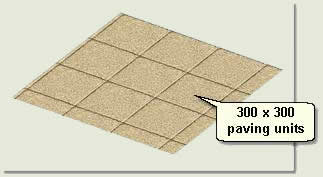
- Open the Material Editor and select the 300x300 stack buff sample window. Notice in the viewport that the paving on the 1m x 1m plane object is 300mm x 300mm paving units
- Anisotropic Basic Parameters rollout. Press the Map Button (This has an M on it to show that there is a map assigned to the material) to go down to the 'Map Level'
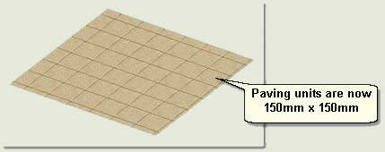
- Coordinates rollout. Change the Tiling to 2 for both the U and V spinners. This halves the tiling and makes the paving units 150mm x 150mm
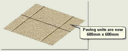
- Coordinates rollout. Change the Tiling to 0.5 for both the U and V spinners. This doubles the tiling and makes the paving units 600mm x 600mm
NOTE: Look at the UVW Map Modifier parameters and notice that the Length and Width are both at 1. These must always be set to 1 if the Map Modifier is to respect the coordinates in the material. Using a 1m x 1m plane object is a good way of setting up pre-tiled materials for paving and walls
- Bitmap Parameters rollout. Note that you can change the Bitmap by pressing the Bitmap button and can view the image (and even crop it) using the View Image button
Adjust the Colour Output in the Material Editor
- Open kf405_02.max again
- Select Plane 01
- Open the Material Editor and select the 300x300 stack buff sample window
- Select the plane object's material and go down to the Map Level as before
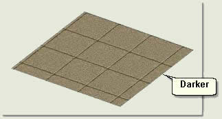
- Output rollout. Check Enable Color Map. This opens up the Color Map
- Move the right hand node down about one third down the graph. Notice in the sample window, the material becomes darker. However, in the viewport there is no change. Render the view and the paving will be darker
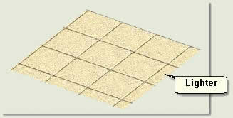
- Move the right hand node up about one third down the graph. Notice in the sample window, the material becomes lighter in the sample window and also when it is rendered
Try these adjustments also:
- Change the Output Amount change the contrast
- Change the RGB Value to change the brightness
- Enable Color Map and check RGB. Select R, G or B toggles above the curve editor and move the right hand nodes up or down to increase or decrease the red, blue or green colour outputs. Keep rendering to see the results. This is great for tweeking material map colours without having to go into an image editor
TIP: When you have finished editing a material leave the material at the highest level (material level) for future editing or to save the material
Donate to CADTutor
If you found this tutorial useful, you might like to consider making a donation. All content on this site is provided free of charge and we hope to keep it that way. However, running a site like CADTutor does cost money and you can help to improve the service and to guarantee its future by donating a small amount. We guess that you probably wouldn't miss $5.00 but it would make all the difference to us.
Local Navigation
Sponsored Links
The Basics
- Dual Dimensions in a Dim…
- UCSICON Options
- "Best of" Basics: Irreg…
- Tool Palette Basics
- Original Dimension Value
- Possible Solutions to th…
- Avoid Using 'Standard' i…
- Shorten the Plot Scales…
- Update the Source File B…
- User Increment Angles fo…
- Drawing Information
- 'Sign Language'
- Rotate with the Copy Opt…
- Use the INSERT Osnap on…
- To or From the Current L…


