

The Material Editor
Introduction
The Material Editor provides functions to create and edit materials and maps. A material is data that you assign to the surface or faces of an object so that it appears a certain way when rendered. Materials affect the colour of objects, their glossiness, their opacity, and so on. The images or procedural effects you assign to materials are called maps. Commonly used maps for landscape work include standard bitmaps (such as .bmp, .jpg, or .tga files) and procedural (meaning they are computer generated) maps, such as Brick or Noise.You can assign maps to most of the components that make up a material. Materials that contain one or more images or procedural maps are called mapped materials
For many map types, the Renderer needs instructions telling it where the map should appear on the geometry. These instructions are called mapping coordinates and are most often handled (apart from loft mapping) by the use of map modifiers. Map coordinates can also be edited in the Material Editor acting on the material itself and most standard primitives have the option of applying map coordinates when the object is created (although these usually need modifying)
Materials create greater realism in a scene. A material describes how an object reflects or transmits light and material properties work hand-in-hand with light properties; rendering combines the two, simulating how the object would look in a real-world setting
This tutorial explores the interface and basic functionality of the Material Editor at the 'Material Level'. This is before adding extra effects with computer generated (procedural) or image maps. The extra effects added at the 'Map' level/s' will be dealt with later
Download Sample Data
kf404_files.zip (16kb)
module_4_maps.zip (5.2mb)
The Interface and basic functionality at the 'Material' level
- Open kf404_01.max. This scene contains some pre-configured materials with which to explore the basic functionality of the Material Editor. Open the Material Editor. The image below shows the mainly used parts of the top interface:
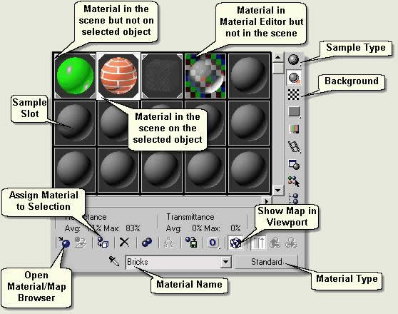
Sample slots
Sample Type
 Select a sample slot by left clicking over it. When the sample slot is current (ie you can edit the material) it shows a white border. Change the Sphere to a Box by clicking the Sample Type Button flyout and choosing the Box Type
Background
 Toggle this button on or off to display a chequered background. This is useful to view how transparent a material is (a glass material for example)
Sample Slot Number
- Right click over any slot to change the number of available slots

Sample Slot Border
The border to each sample slot shows the status of the materials in the editor thus:
- White border means the sample slot is current ie the material can be edited
- White triangles not filled means the material exists in the scene (assigned to an object) but no objects with that material are selected
- White triangles filled means the material in the slot is assigned to a selected object
Toolbar
 Press Get Material. This opens the Material/Map Browser. This is where you manage material and map resources in and out of the scene
 Select the Box and in the Material Editor select the Brick material sample slot. Press Assign Material to Selection. Notice in the viewport the box is assigned the brick material
 Press Show Map in Viewport. This shows the brick map which is part of the Brick material in the viewport or not. Toggle this on and off and notice the bricks on the box are shown or not shown
 Press Put to Library. This opens a dialog box for saving the current material to a material library. Close the box as this is explained later
 Go to Parent is used when you are at the 'Map' level (accessed through pressing one of the Map buttons - explained later) to return to the next level up in the material. This is greyed out if no Maps are used in the material
TIP: You can remove a materiall completely from an object in the scene by dragging the NONE item from the Material / Map Browser over to the object
 Select an empty sample slot and press Pick Material from Object. This is a quick way to select a material in the scene for editing purposes
Material Name
Type the name of the current material in this text box
Material Type
The Material Type is at the top of the hierarchy when you create or edit materials. Standard is the default material type in MAX and Architectural is the default material in Autodesk VIZ (this has been changed to Standard for this exercise)
 Press this button (in MAX) or the button displaying ‘Architectural’ (in VIZ) to open the Material/Map Browser and to pick from a selection of Material Types. The most common for landscape use are Standard (most materials including none mapped and mapped materials - procedural maps and image maps), Double Sided (contains two standard materials for the front and back of a road sign for example) and Multi > Sub-Object (for use on any objects that contain a number of elements needing different materials assigned to each element - a seat with painted legs and wood slats for example)
- If you are using VIZ select Standard and press Ok as we are going to explore the use of Standard materials
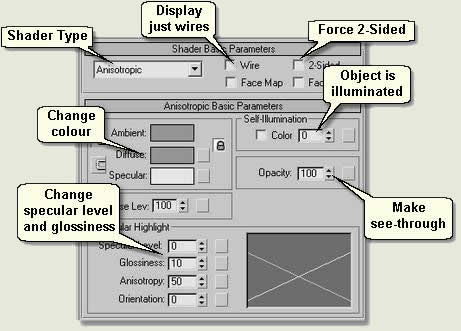
- The next step is to look at the shader type thus:
Shader Parameters
- Select a new sample slot
- Change the shader type to Anisotropic - this together with Metal are well used in landscape work. Shaders give different basic settings for materials. Explore the other shaders using the MAX/VIZ help system. The most useful settings for the Anisotropic shader are shown above
- Name the material 'Practice'
- Select the sphere and Assign Material to Selection. This assigns a Standard, unedited material using the Anisotropic shader
Shader Basic Parameters rollout
These settings apply to any shader
- Check Wire and toggle this on and off to display the sphere in wireframe. If you change the amount of segments in the sphere the wires change as well. Uncheck this before proceeding
- Checking 2-Sided forces the material to become 2-sided. This is the third (apart fronm the Viewport Configuration and Render Scene dialogs) place you can make an object 2-sided
Anisotropic Basic Parameters rollout
- Click the colour swatch to the right of Diffuse to change the colour of the sphere
NOTE: The Ambient swatch changes as well as the Diffuse swatch. This can be unlocked by pressing the lock button to the left of the Diffuse and Ambient swatches. The Ambient light can then be changed independantly
- Change the Specular Level to 75 and Glossiness to 50. This gives the material a look of gloss paint or plastic. You could name this 'Blue Paint' for example and save the material for use in many scenes (explained later)
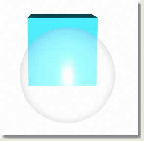
- Change the Diffuse colour to light yellow and the Self-illumination to 80. This simulates a lamp and will show as illuminated in a night scene. A light would be placed in the lamp. Change back to 0 before proceeding
- Change Opacity to 40. This makes the sphere translucent. Used in conjunction with the other settings (especially Specular Level and Glossiness) a simple glass material can be created. Look at the settings in the Glass material for reference
As you can hopefully envisage, many materials can be created by simply using the basic shader parameters
NOTE: Assigning a material to an object removes any existing material assigned to the object and replaces it. Also, a material can be quickly assigned to an object by dragging it from the sample slot to the object in the viewport
Extended Parameters rollout

- With Wire selected in Basic Shader Parameters change the size of the wire on this rollout
SuperSampling rollout
This is not covered in Key Fundamentals, but for information this allows more sampling of any images in the material at render time. It stops any 'shimmering, or distortion throughout animation sequences, and gives better quality renders for still images. Because the render time is greater a good handle of the supersampling settings is needed to obtain an optimum balance between quality and render time. Settings can be changed in both the material and on the Render Scene dialog
Maps rollout
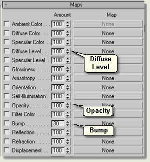
This is where various maps can be applied to the material. In landscape work the most used maps are applied to the Diffuse Level (all landscape materials) plus perhaps Opacity (for masking buildings, signs, vegetation etc images) and > or Bump (for giving relief to walls and paving)
- Press the Map Button showing 'None' to the right of any of these Map types to open the Material/Map Browser. For now, just have a look at the types of maps available
Donate to CADTutor
If you found this tutorial useful, you might like to consider making a donation. All content on this site is provided free of charge and we hope to keep it that way. However, running a site like CADTutor does cost money and you can help to improve the service and to guarantee its future by donating a small amount. We guess that you probably wouldn't miss $5.00 but it would make all the difference to us.
Local Navigation
Sponsored Links
The Basics
- Dual Dimensions in a Dim…
- UCSICON Options
- "Best of" Basics: Irreg…
- Tool Palette Basics
- Original Dimension Value
- Possible Solutions to th…
- Avoid Using 'Standard' i…
- Shorten the Plot Scales…
- Update the Source File B…
- User Increment Angles fo…
- Drawing Information
- 'Sign Language'
- Rotate with the Copy Opt…
- Use the INSERT Osnap on…
- To or From the Current L…


