All Activity
- Today
-
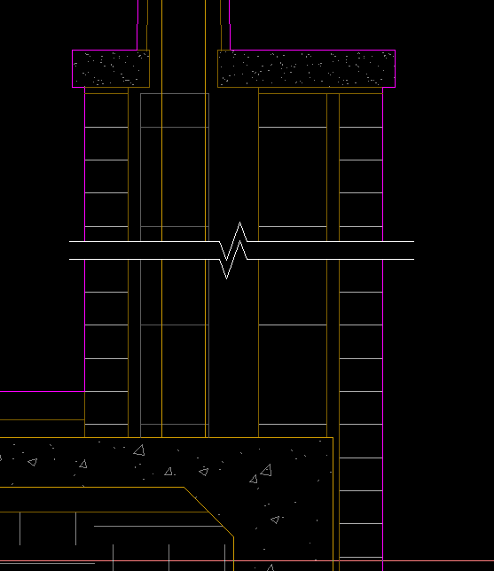
I use a block with mask/wipeout, scaled up, then xclipped to trim the extent of lines. Allows easy moving and 'breaking' of hatch patterns without actually breaking anything. sym-breakline-mask.dwg

-
 rendar70 joined the community
 -
 TheOnCourseEngineers joined the community
 -
 aburnett77 joined the community
 -

AL's Steel Mill not working on BricsCAD
Lee Mac replied to Jgrand3371's topic in AutoLISP, Visual LISP & DCL
What error message(s) do you receive, if any? -

Choose which attributes to display in Block Reference.
CyberAngel replied to fromMlm's topic in AutoCAD Drawing Management & Output
Not sure if this will work the way you want. I created a dummy drawing with a dummy block and a dummy attribute. When you set the attribute to Invisible, you can't see it any more, but you can edit it. I know, that's not what you want. I include it so you don't waste time trying it for yourself. When you set the attribute to Constant, you can't edit it at all. It no longer shows up in the Properties, and it doesn't show up in the block. If you change the attribute back to not constant, you can insert a new block and give it a different value, but it's still invisible and it does show up in Properties. Could be a bug? Or the way I handled it. -

Vehicle Tracking - where to find details for vehicles
Steven P replied to Adam - Inspire's topic in Autodesk Software General
Thanks, looked at this before but CADtools are a special request for us, probably needs signing off by some deity or other -
Vehicle Tracking - where to find details for vehicles
Steven P replied to Adam - Inspire's topic in Autodesk Software General
Thanks BigAl, I was mistaken yesterday, thought AutoTurn had been taken on by AutoCAD so didn't look more into it... but it is a 3rd party add on - looks good and a minimal cost... but for this not sure 'IT' would let me have it... but I'll put in a request... you never know and always good to have new toys to play with -

AL's Steel Mill not working on BricsCAD
SLW210 replied to Jgrand3371's topic in AutoLISP, Visual LISP & DCL
Since this is unrelated to the original post updating the AISC Steel Shapes, I have created a new thread AL's Steel Mill not working on BricsCAD in the AutoLISP, Visual LISP & DCL Forum. -
Vehicle Tracking - where to find details for vehicles
SLW210 replied to Adam - Inspire's topic in Autodesk Software General
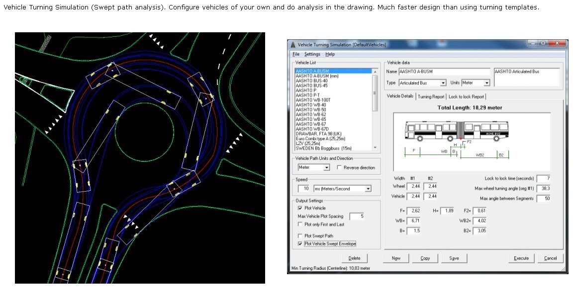
I use the one in CadTools and it has window that opens and you can adjust the parameters and create a custom vehicle.
-

Choose which attributes to display in Block Reference.
fromMlm posted a topic in AutoCAD Drawing Management & Output
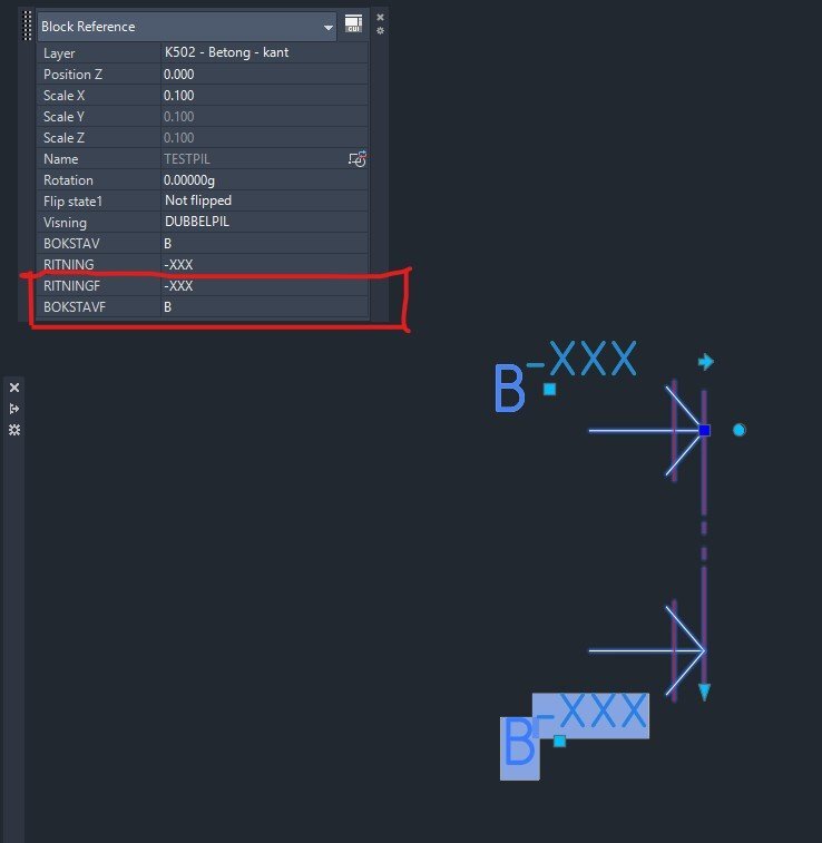
Hi I have two attributes as fields which i dont want to show/display in the Block Reference window. See screenshot. How do I make them disapear there so you dont accidentally change them? Kindly regards Section marker.dwg
- Yesterday
-

Vehicle Tracking - where to find details for vehicles
BIGAL replied to Adam - Inspire's topic in Autodesk Software General
Many years ago now I think it was "Autoturn" it popped up a dcl/picture that you put all the values into, so just found one close first and printed it, that gave what values went where. Was it also "Vehicle tracking" by Autodesk ? -
Have you looked at: https://www.lee-mac.com/batte.html
- 1 reply
-
- 1
-

-

AL's Steel Mill not working on BricsCAD
JerryFiedler replied to Jgrand3371's topic in AutoLISP, Visual LISP & DCL
@Jgrand3371 I just loaded the app onto my BrisCAD Pro V26 and it appears to work. I just tested a few of the many options, certainly not an extensive test. This program is great! @gtwatson Thank you for sharing. -
 nkh503 joined the community
 -
Vehicle Tracking - where to find details for vehicles
Steven P replied to Adam - Inspire's topic in Autodesk Software General
Going to resurrect an old thread.... Going to have to do some vehicle tracking this week or next, articulated lorry but extended trailer. I have a PDF of the dimensions. Is there an easy to follow guide out there that shows what values to put where to convert a CAD drawing into a vehicle tracked vehicle? Thanks (My first attempts this morning had the trailer pointing out the front, cutting the driver in half). I guess I can work it out trial and error but jumping that part. And second question which is my default model for new tools, does anyone have an x wing fighter modelled as a 'vehicle'? That might be a weekend thing. Thanks -
I currently am struggling with this issue. There are many ways to update all component attributes within the drawing I'm in. ATTOUT/ATTIN works great for updating all of the necessary information within the active drawing. However, it does not push this update throughout the project to the other instances of the same component tags. I am not sure if this is the correct place to ask for assistance, but I need help figuring out how to force an update to the rest of the project based on the information in the current drawing. Otherwise I have to edit every single component on one drawing, and then utilize task list to update the other drawings, or I have to update every single drawing with ATTOUT/ATTIN. I'm looking for something that would allow a bulk edit of each tags attributes that will also sync project wide.
-
 KStag joined the community
 -
 You need to start a new thread in the AutoLISP, Visual LISP & DCL Forum.
 -
 Biana_058 joined the community
 -
https://github.com/mapbox/concaveman https://github.com/sadaszewski/concaveman-cpp it’s not automatic in that it requires parameters depending on the point distribution. concavity: A relative measure of concavity. A value of 1 provides a detailed shape, while Infinity results in a convex hull. lengthThreshold: Determines the minimum segment length considered for further detailing, with higher values leading to simpler shapes. Chomped through this 280k point set import traceback from pyrx import Ap, Db, Ed, Ge # --- Command for PyRx --- @Ap.Command() def doit0(): try: ps, ss = Ed.Editor.select([(Db.DxfCode.kDxfStart, "POINT")]) pnts = Ge.Point3dArray([Db.Point(id).position() for id in ss]) hull_points = pnts.concaveHull(0.8, 100) db = Db.curDb() pl = Db.Polyline(hull_points) pl.setDatabaseDefaults() pl.setClosed(True) pl.setColorIndex(2) db.addToModelspace(pl) except Exception: traceback.print_exc()
-
- 1
-
-

Python, A Very high performance Delaunay triangle algorithm
Danielm103 replied to Danielm103's topic in .NET, ObjectARX & VBA
This is a great guide working with Delaunator. https://mapbox.github.io/delaunator/ It explains the relationship between half-edges and triangles. in short the triangles are created in an order, you can iterate the triangles while being aware of the adjacent triangles. A [-1] in the half edge list means that edge is on the outside hull. -
Python, A Very high performance Delaunay triangle algorithm
Danielm103 replied to Danielm103's topic in .NET, ObjectARX & VBA
The algorithm is fast because it returns a list of indexes, to your original array, of the points that make up the triangle, it also returns a list of half edges from pyrx import Ap, Db, Ed, Ge, Gi import traceback @Ap.Command() def doit(): try: filter = [(Db.DxfCode.kDxfStart, "POINT")] ps, ss = Ed.Editor.selectPrompt( "\nSelect points: ", "\nRemove points: ", filter ) if ps != Ed.PromptStatus.eNormal: return pnts = Ge.Point3dArray([Db.Point(id).position() for id in ss]) d = Ge.Delaunator(pnts) print(d.triangles()) print(d.halfedges()) except Exception: print(traceback.format_exc()) [0, 4, 3, 2, 1, 0, 0, 1, 4, 3, 2, 0] [8, -1, 11, -1, 6, 10, 4, -1, 0, -1, 5, 2] -
Python, A Very high performance Delaunay triangle algorithm
Danielm103 posted a topic in .NET, ObjectARX & VBA
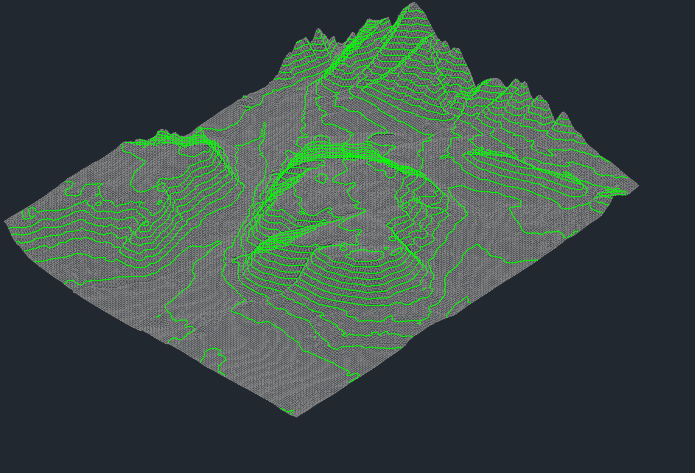
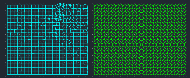
the sample import traceback from time import perf_counter from pyrx import Ap, Db, Ed, Ge # Ge.Delaunator uses a modified version of https://github.com/abellgithub/delaunator-cpp. # Its modified in that it’s designed to use a collection of Ge.Point3d. # its documented here https://mapbox.github.io/delaunator/ # Also see https://github.com/mapbox/delaunator, https://github.com/HakanSeven12/Delaunator-Python # ---------------------------------------------------------------------- # Module: PyRx Voronoi & Delaunator Tools # Description: Provides AutoCAD commands to generate Voronoi diagrams # (using Circumcenters and Centroids) and Delaunay triangulation # with contour line generation. # ---------------------------------------------------------------------- print("added command pyvoronoiCCM") print("added command pyvoronoiCEN") print("added command pydelaunator") # ---------------------------------------------------------------------- # Helper Functions # ---------------------------------------------------------------------- def do_select(): """ Prompts the user to select AutoCAD POINT entities. Returns: Ed.SelectionSet: The selected set if successful, None otherwise. """ # Define a filter to only select POINT entities filter = [(Db.DxfCode.kDxfStart, "POINT")] # Prompt user for selection and removal # Returns (PromptStatus, SelectionSet) ps, ss = Ed.Editor.selectPrompt("\nSelect points: ", "\nRemove points: ", filter) if ps == Ed.PromptStatus.eNormal: return ss return None def circumcenter(a: Ge.Point3d, b: Ge.Point3d, c: Ge.Point3d): """ Calculates the circumcenter of a triangle defined by three points. The circumcenter is the center of the circle that passes through all three vertices. It is calculated using vector algebra (barycentric coordinates). Args: a (Ge.Point3d): First vertex b (Ge.Point3d): Second vertex c (Ge.Point3d): Third vertex Returns: Ge.Point3d: The circumcenter of the triangle. """ ac: Ge.Vector3d = c - a ab: Ge.Vector3d = b - a # Cross product of AB and AC abXac = ab.crossProduct(ac) # Vector calculation for the circumcenter # Formula: (|AC|^2 * (AB x (AB x AC)) + |AB|^2 * ((AB x AC) x AC)) / (2 * |AB x AC|^2) cc = ( abXac.crossProduct(ab) * ac.lengthSqrd() + ac.crossProduct(abXac) * ab.lengthSqrd() ) # Normalize and translate to point A toCircumsphereCenter = cc / (2.0 * abXac.lengthSqrd()) return a + toCircumsphereCenter def centroid(a: Ge.Point3d, b: Ge.Point3d, c: Ge.Point3d): """ Calculates the centroid (geometric center) of a triangle. The centroid is the arithmetic mean position of all the points in the figure. Args: a (Ge.Point3d): First vertex b (Ge.Point3d): Second vertex c (Ge.Point3d): Third vertex Returns: Ge.Point3d: The centroid of the triangle. """ CX1 = (a.x + b.x + c.x) / 3 CX2 = (a.y + b.y + c.y) / 3 CX3 = (a.z + b.z + c.z) / 3 return Ge.Point3d(CX1, CX2, CX3) def triangle(idx: int, d: Ge.Delaunator, pnts: list[Ge.Point3d]): """ Helper to extract the three vertices of a specific triangle from the Delaunator data. Args: idx (int): Index of the triangle in the flat array (every 3rd index is a new triangle). d (Ge.Delaunator): The Delaunator object. pnts (list): List of input points. Returns: list: A list of three Ge.Point3d objects. """ triangles = d.triangles() return [ pnts[triangles[idx + 0]], pnts[triangles[idx + 1]], pnts[triangles[idx + 2]], ] def triangleAtEdge(e: int): """ Determines the index of the adjacent triangle sharing a half-edge. The Delaunator stores triangles in a flat array. Each edge is shared by two triangles. This function calculates the index of the other triangle based on the half-edge index. Args: e (int): The half-edge index. Returns: int: The index of the adjacent triangle. """ if e % 3 == 1: return e - 1 elif e % 3 == 2: return e - 2 return e def get_3dpointds(objs: list[Db.ObjectId]): """ Extracts the 3D position of selected objects. Args: objs (Ed.SelectionSet): The selection set containing POINT entities. Returns: list: A list of Ge.Point3d objects. """ pnts = [] for id in objs: p = Db.Point(id) pnts.append(p.position()) return pnts # ---------------------------------------------------------------------- # Voronoi Generation Functions # ---------------------------------------------------------------------- def getVoronoiEdgesCCM(d: Ge.Delaunator, pnts: list[Ge.Point3d]): """ Generates Voronoi edges using the Circumcenter (CCM) method. For every edge shared by two triangles, the circumcenter of each triangle is calculated. The line connecting these two circumcenters is a Voronoi edge. Args: d (Ge.Delaunator): The Delaunator object. pnts (list): List of input points. Returns: list: A list of tuples, where each tuple contains two Ge.Point3d (start, end). """ edges = [] triangles = d.triangles() halfedges = d.halfedges() # Iterate through the flat triangle array (step 3 for each triangle) for i in range(0, len(triangles), 3): tri1 = triangle(i, d, pnts) # Calculate circumcenter of the current triangle p = circumcenter(tri1[0], tri1[1], tri1[2]) # Check each of the 3 edges of the triangle for o in range(3): if halfedges[i + o] != -1: e = halfedges[i + o] nt = triangleAtEdge(e) # Ensure the adjacent triangle exists if nt < len(triangles): tri2 = triangle(nt, d, pnts) q = circumcenter(tri2[0], tri2[1], tri2[2]) edges.append((p, q)) return edges def getVoronoiEdgesCEN(d: Ge.Delaunator, pnts: list[Ge.Point3d]): """ Generates Voronoi edges using the Centroid (CEN) method. Similar to CCM, but uses the geometric centroid of the triangle instead of the circumcenter. Args: d (Ge.Delaunator): The Delaunator object. pnts (list): List of input points. Returns: list: A list of tuples, where each tuple contains two Ge.Point3d (start, end). """ edges = [] triangles = d.triangles() halfedges = d.halfedges() for i in range(0, len(triangles), 3): tri1 = triangle(i, d, pnts) # Calculate centroid of the current triangle p = centroid(tri1[0], tri1[1], tri1[2]) for o in range(3): if halfedges[i + o] != -1: e = halfedges[i + o] nt = triangleAtEdge(e) if nt < len(triangles): tri2 = triangle(nt, d, pnts) q = centroid(tri2[0], tri2[1], tri2[2]) edges.append((p, q)) return edges # ---------------------------------------------------------------------- # Contour Generation Functions # ---------------------------------------------------------------------- def interpolate_point(p1, p2, level): """ Linearly interpolates a point on a line segment at a specific Z level. Args: p1 (list): Start point [x, y, z] p2 (list): End point [x, y, z] level (float): The Z elevation to interpolate to. Returns: list: The interpolated point [x, y, z]. """ t = (level - p1[2]) / (p2[2] - p1[2]) return [p1[0] + t * (p2[0] - p1[0]), p1[1] + t * (p2[1] - p1[1]), level] def process_triangle_contours(triangle_points: list[Ge.Point3d], level: float): """ Processes a single triangle to generate contour segments at a specific Z level. Checks which vertices are below and above the level, then interpolates the intersection points on the edges. Args: triangle_points (list): List of 3 points [x, y, z]. level (float): The Z level to generate contours for. Returns: list: A list of interpolated contour points, or None if no intersection occurs. """ points_below = [] points_above = [] for point in triangle_points: if point[2] < level: points_below.append(point) else: points_above.append(point) # No intersection if all points are on one side if len(points_below) == 0 or len(points_above) == 0: return None contour_points = [] # Case 1: One point below, two above -> Interpolate two edges if len(points_below) == 1: p1 = points_below[0] p2, p3 = points_above contour_points = [ interpolate_point(p1, p2, level), interpolate_point(p1, p3, level), ] # Case 2: Two points below, one above -> Interpolate two edges elif len(points_below) == 2: p1, p2 = points_below p3 = points_above[0] contour_points = [ interpolate_point(p1, p3, level), interpolate_point(p2, p3, level), ] return contour_points # ---------------------------------------------------------------------- # AutoCAD Commands # ---------------------------------------------------------------------- @Ap.Command() def pyvoronoiCCM(): """ AutoCAD Command: pyvoronoiCCM Generates a Voronoi diagram using Circumcenters. """ try: ss = do_select() if not ss: return t1_start = perf_counter() pnt3ds = get_3dpointds(ss) # Perform Delaunay triangulation d = Ge.Delaunator(pnt3ds) # Generate Voronoi edges for e in getVoronoiEdgesCCM(d, pnt3ds): # Draw the edge using the Graphics API Ed.Core.grDraw(e[0], e[1], 4, 0) t1_stop = perf_counter() print("Elapsed time: {t:.4f}".format(t=t1_stop - t1_start)) except Exception as err: traceback.print_exception(err) @Ap.Command() def pyvoronoiCEN(): """ AutoCAD Command: pyvoronoiCEN Generates a Voronoi diagram using Centroids. """ try: ss = do_select() if not ss: return t1_start = perf_counter() pnt3ds = get_3dpointds(ss) # Perform Delaunay triangulation d = Ge.Delaunator(pnt3ds) # Generate Voronoi edges for e in getVoronoiEdgesCEN(d, pnt3ds): # Draw the edge using the Graphics API Ed.Core.grDraw(e[0], e[1], 3, 0) t1_stop = perf_counter() print("Elapsed time: {t:.4f}".format(t=t1_stop - t1_start)) except Exception as err: traceback.print_exception(err) @Ap.Command() def pydelaunator(): """ AutoCAD Command: pydelaunator Generates Delaunay triangles and contour lines based on point Z values. """ try: ss = do_select() if not ss: return t1_start = perf_counter() pnt3ds = get_3dpointds(ss) # Perform Delaunay triangulation t = Ge.Delaunator(pnt3ds).triangles() # Calculate min/max Z values for contour generation ncontours = 20 z_values = [p[2] for p in pnt3ds] min_z = min(z_values) max_z = max(z_values) step = (max_z - min_z) / ncontours contour_lines = [] # Generate contour lines for each elevation level for level in [min_z + i * step for i in range(1, ncontours)]: for i in range(0, len(t), 3): triangle_points = [pnt3ds[t[i]], pnt3ds[t[i + 1]], pnt3ds[t[i + 2]]] contour_segment = process_triangle_contours(triangle_points, level) if contour_segment: contour_lines.append(contour_segment) db = Db.HostApplicationServices().workingDatabase() model = Db.BlockTableRecord(db.modelSpaceId(), Db.OpenMode.kForWrite) # Draw triangles for i in range(0, len(t), 3): f = Db.Face(pnt3ds[t[i]], pnt3ds[t[i + 1]], pnt3ds[t[i + 2]]) f.setColorIndex(8) # Color 8 is usually White/Light Gray model.appendAcDbEntity(f) # Draw contours segs = [] for contour in contour_lines: segs.append(Ge.LineSeg3d(Ge.Point3d(contour[0]), Ge.Point3d(contour[1]))) # Convert line segments to a CompositeCurve and then to AutoCAD Curve entities ccs = Ge.CompositeCurve3d.createFromLineSeg3dArray(segs) for cc in ccs: dbc = Db.Core.convertGelibCurveToAcDbCurve(cc) dbc.setColorIndex(3) # Color 3 is usually Cyan model.appendAcDbEntity(dbc) t1_stop = perf_counter() print("Elapsed time: {t:.4f}".format(t=t1_stop - t1_start)) except Exception as err: print(err)
-

PDF/ JPG file conversion threat.
EleenD03 replied to nidhi singhania's topic in AutoCAD 2D Drafting, Object Properties & Interface
That’s a fair point about the security risks with random online converters. I’ve definitely noticed that some of the free sites get really 'spammy' or trigger browser warnings lately. I usually try to stick to the built-in 'DWG to PDF' plotter in AutoCAD to keep things clean, but if I’m looking for specific educational templates or tracing layouts for the kids to practice with, I've found it's better to use dedicated niche sites rather than generic converters. I recently came across https://nametracingpdf.com/ for some clean practice sheetsit's a good example of getting a direct PDF without having to jump through those 'convert-this-file' hoops that usually carry the malware risks you’re talking about. - Definitely pays to be cautious where you upload your project files! - Last week
-

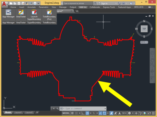
TotalBoundary • Outline creation tool
CraneGuy commented on Debalance's file in Programs and Scripts
I appreciate your response. I even tried calling the number listed on the domain registration! No reply unfortunately. I used all the workarounds prior to finding TB, but the one click nature of it was invaluable. I messaged Lee Mac to see if he was interested in recreating TB...hopefully he'll be interested in adding the WIPEOUT element. -
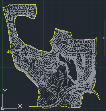
No activity for a few years now and no responses on any forums/email, so could be anything. You might try Lee Mac's LISP. Some verticals have the SHRINKWRAP command, if you have the FREE tool pack and Architecture, it has SHRINKWRAP. You could create hatches, then a boundary and delete the hatches or just have them on a Frozen or No Plot layer.
-
AL's Steel Mill not working on BricsCAD
SLW210 replied to Jgrand3371's topic in AutoLISP, Visual LISP & DCL
It might help to provide a lot more information. Where did you get the LISP and what version? What exactly is the meaning of "most of my lisp routines work, but this one does not."? Should be some sort of error or doesn't load correctly, etc. if no error shown in CAD, try to run an error checker in your code editor. Do you have everything in a pathed folder? -
Thought I had posted this a dcl front end. (defun inputinfo ( / AH:setvals dcl des) (defun AH:setvals ( / ) (if(= (get_tile "Rb1") "1") (setq ztype "S") (setq ztype "D") ) (cond ((= (get_tile "Rb3") "1")(setq extop "F")) ((= (get_tile "Rb4") "1")(setq extop "P")) ((= (get_tile "Rb5") "1")(setq extop "N")) ) (setq extlen (atof (get_tile "val1"))) (princ) ) (setq dcl (vl-filename-mktemp "" "" ".dcl")) (setq des (open dcl "w") ) (foreach x '( "brklines : dialog {" " label =\"Please choose\" ;" " : row {" " : boxed_radio_column {" " width = 23 ;" " label =\"Single or Double\" ;" "spacer_1 ;" " : radio_button {" "key = \"Rb1\";" "label = \"Single\" ;" " }" "spacer_1 ;" " : radio_button {" "key = \"Rb2\";" "label = \"Double\" ;" " }" "spacer_1 ;" " }" " }" " : row {" " : boxed_radio_column {" " width = 23 ;" " label =\"Extend beyond picked points\" ;" "spacer_1 ;" " : radio_button {" "key = \"Rb3\";" "label = \"Fixed\" ;" " }" "spacer_1 ;" " : radio_button {" "key = \"Rb4\";" "label = \"Proportional\" ;" " }" "spacer_1 ;" " : radio_button {" "key = \"Rb5\";" "label = \"None\" ;" " }" "spacer_1 ;" " }" " }" " : row {" ": edit_box {" " label = \"Extension length\" ;" "spacer_1 ;" " width = 25 ;" "key = \"val1\" ;" " edit_width = 10 ;" " edit_limit = 9 ;" " is_enabled = true ;" " allow_accept=true ;" " }" " }" "spacer_1 ;" " ok_cancel ;" " }" ) (write-line x des ) ) (close des) (setq dcl_id (load_dialog dcl)) (if (not (new_dialog "brklines" dcl_id) ) (exit) ) (set_tile "Rb1" "1") (set_tile "Rb3" "1") (set_tile "val1" "50.0") (action_tile "accept" "(AH:setvals)(done_dialog)") (action_tile "cancel" "(done_dialog)(exit)") (start_dialog) (unload_dialog dcl_id) (vl-file-delete dcl) (princ) ) (inputinfo)
-
I use this tool on a daily basis, so thank you for the update. I'm testing a trial version of Bricsys and most of my lisp routines work, but this one does not. Has anyone gotten it to work successfully in Bricsys?
-

Dimangular-Vertex Macro Error
zaphod replied to zaphod's topic in The CUI, Hatches, Linetypes, Scripts & Macros
My fault for not stating all the angles were to be measured CW or CCW from 0°.