All Activity
- Past hour
-
 Jesper Hedlund joined the community
 -

Set Pline Z value by selecting text
pkenewell replied to PaulyPHI's topic in AutoLISP, Visual LISP & DCL
@darshjalal Nice work! Your added Automatic mode, and the code to strip numbers out of the text is over and above! -
Set Pline Z value by selecting text
pkenewell replied to PaulyPHI's topic in AutoLISP, Visual LISP & DCL
@PaulyPHI Here is a quick walk-though: This uses Visual LISP to pull the text string from the selected object and convert it to a real number. See the added comments below. (if (and ;; Logical AND = All conditions must be met. ;; 1) an object must be selected. (setq es (entsel "\nSelect Text Object: ")) ;; 2) The selected object must have a text string property, i.e. TEXT, MTEXT, ATTRIBUTE, MLEADER, etc. (vlax-property-available-p (vlax-ename->vla-object (car es)) 'TextString) ;; 3) Retrieve the textsting value if the above conditions are met. (setq newZ (vla-get-textstring (vlax-ename->vla-object (car es)))) ;; 4) The textstring value must evaluate to greater than 0 when converted to a real number. This only works if the text is numerical. (> (setq newZ (atof newZ)) 0.0) ) ;; if all conditions are met, then continue to the (progn) block that performs the changes. - Today
-
 Bill Wan joined the community
 -

Automatically placing borehole tables with leaders without overlap
mhupp replied to MSHR's topic in AutoLISP, Visual LISP & DCL
Welcome. To make a cleaner look I would make a master Chart (or multiple BH SW MW or by area with a box around them) with all the relative call outs. this would allow a larger view of the area. eliminate the use/need of leaders that aren't really doing anything but cluttering the drawing. -edit Then updating would be adding borehole location and adding to the chart.- 1 reply
-
- 1
-

-

Having some issues converting to 3d
TimC replied to TimC's topic in AutoCAD 3D Modelling & Rendering
I agree 100% I've been on several of the "free STL" sites and that stuff is nice, especially for new people, but I like the satisfaction of knowing I built that and you're definitely right with some of that stuff needing tweaked. I've run into that a few times. I have a Flashforge AD5X and I'm still learning to use the software. If I remember correctly, I just used the STLOUT command to export the file from AutoCAD, then I open Flashforge and click/drag it from my desktop onto my slicer -

Having some issues converting to 3d
SLW210 replied to TimC's topic in AutoCAD 3D Modelling & Rendering
Like I stated, I still like leaning on AutoCAD for making things for the 3D printer, but also learning Blender and playing with TinkerCAD, etc. The main goal is getting nice 3D Prints, I can tell you from experience, the stuff you get from online, supposedly ready to print, sometimes needs a little tweaking or outright re-modeled. I also have been learning to work in the 3D printer software, in my case, Bambu Studio, it's a lot easier cleaning up, scaling, adding text, etc. right before slicing. Like anyone that uses tools to do a job, learning what tools to use, how to use them, when to use what, etc. is usually the best way to go forward, it's a learning process. By all means start with AutoCAD and improve, we are here to help. Do you know how to export to STL and import that into your slicer? -
Having some issues converting to 3d
TimC replied to TimC's topic in AutoCAD 3D Modelling & Rendering
I messed around a little with tinker cad but figured since I already had some knowledge of AutoCAD that it would probably be more useful to stick with AutoCAD. as I mentioned above, I just started learning AutoCAD in November of last year through Penn Foster (don't hold that against me. I'm basically teaching myself at this point with the help of you fellas). -
Having some issues converting to 3d
TimC replied to TimC's topic in AutoCAD 3D Modelling & Rendering
Well, I just started learning AutoCAD in November of last year through Penn Foster (don't hold that against me. I'm basically teaching myself at this point with the help of you fellas). I didn't realize you could set the text height BEFORE you press pull. I just started the press/pull then typed the number I want. As far as architectural, I'll be honest, that's all we used when I was in college so that's all I really know -
Having some issues converting to 3d
SLW210 replied to TimC's topic in AutoCAD 3D Modelling & Rendering
Did you try doing these in TinkerCAD? Not sure why your have issues with exploding the text in AutoCAD, I'll look when I get back to work tomorrow. Even as you describe it "When I tried txtexp it shot the text way off to the left and made it huge", you just have to move it and scale it. What you really want to do is learn to do this with the 3D Printer tools. https://www.youtube.com/watch?v=9McpK4nNf2k -
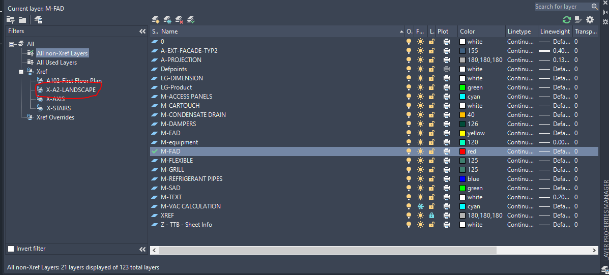
Thank you, but I am looking for something more general (I don’t think a LISP will solve the problem). I remember seeing something on YouTube where we can control layer properties without opening the drawings. I uploaded the picture for this specific XREF (x-A2-landscape). I don’t want to change these properties for this xref ....... Your LISP is too specific because, on some floors, more or fewer architectural XREFs are attached.

-

Set Pline Z value by selecting text
PaulyPHI replied to PaulyPHI's topic in AutoLISP, Visual LISP & DCL
Thank you very much sir, works perfect. I have compared the modified text file to the original and my brain just melted.... i can see some text that makes sense but the rest is just gobldee goop to me.... I'm just not programmed to understand it... Thank you once again. -
 Tutor-desk joined the community
 -
 ybr joined the community
 -

EGBoundary – Boundary Generation Tool for Complex 2D CAD Drawings.
Aniruddha posted a file in Programs and Scripts

Version 1.0.9637
4 downloads
EGBoundary is a CAD plugin designed to generate clean outer boundaries from complex 2D drawings. It is intended for situations where standard boundary creation methods may struggle due to: small gaps overlapping geometry dense drawings complex spline/arc combinations EGBoundary is designed to simplify boundary creation workflows and reduce the amount of manual cleanup and time often required in complex drawings. Workflow Overview: Type EGBOUNDARY (Case Insensitive) on command line. Select the drawing geometry Configure tolerance/output settings if required by typing ' S ' on command line Press enter to generate the outer boundary polyline Demonstration Video: CADTEGB.mp4 Key Features: Generates clean closed outer boundaries from selected geometry. Automatic and manual tolerance handling. Supports multiple outer boundary detection from a single selection. Custom output layer and color options. Custom linetype options. Works with large and complex drawings containing many entities. Supports lines, arcs, splines, ellipses, polylines, and blocks. Supports Wipeout generation. Compatibility: AutoCAD BricsCAD GstarCAD ZWCAD Official Website: For more information, updates, documentation, or EGBoundary for other CAD platforms, please visit: Official Website For EGBOUNDARY For any queries related to EGBoundary or CAD customization, feel free to reach out to us at: contact@engenext.com or aniruddha.raste@engenext.com Would really appreciate feedback, suggestions, or difficult test cases from the community. -

Having some issues converting to 3d
BIGAL replied to TimC's topic in AutoCAD 3D Modelling & Rendering
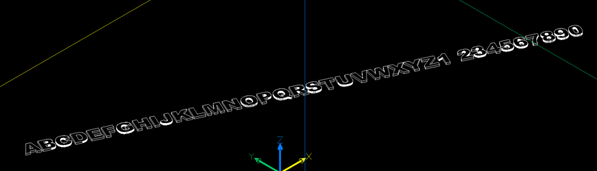
Don't know what is going on about Textexp but here is a favour for you. I just made A-Z 0-9 exploded. Convert to correct plines then can extrude into a solid say 1 unit high, will need to check the 36 shapes. The sample dwg really needs more thought say text size =1 and height equal say 0.1. It took about 10 minutes to make these. With a bit of practice much faster and use other fonts. You can use presspull to change height. BUT SET TEXT HEIGHT CORRECT BEFORE EXTRUDE. Oh yeah why do you have units set to Architectural when your talking mm ? new block.dwg
-

LISP CODE INSERTING ELEVATION FROM CIVIL 3D SURFACE TO 3DPOLYLINES
darshjalal replied to darshjalal's topic in AutoLISP, Visual LISP & DCL
Becaus I don't want the drawing to be denser especially when trying calculate the earthwork for a raft with huge number of drops That is why I made this code. -
So give this a try. Just load the xrefs in a dwg then run this code will reset all the xref layers. Note will do all current XREFS. Just do it as part of adding the XREFS to current dwg. ; https://www.cadtutor.net/forum/topic/99138-layer-properties/ ; Set all xref colors in a dwg ; By AlanH May 2026 (defun c:setxrefcol ( / lst blk lays xname tc) (setq lst '()) (setq blk (tblnext "BLOCK" T)) (while blk (if (member (logand (cdr (assoc 70 blk)) 4) '(4)) ; bit‑4 = xref (setq lst (cons (cdr (assoc 2 blk)) lst)) ) (setq blk (tblnext "BLOCK")) ) (reverse lst) (setq lays (vla-get-layers (vla-get-activedocument (vlax-get-acad-object)))) (repeat (setq x (length lst)) (setq xname (nth (setq x (1- x)) lst)) (vlax-for lay lays (setq lname (vlax-get lay 'name)) (if (wcmatch lname (strcat "*" lname "*")) (progn (setq tc (vla-GetInterfaceObject (vlax-get-acad-object) "AutoCAD.AcCmColor.20")) (vla-SetRGB tc 180 180 180) (vla-put-TrueColor lay tc) ) ) ) ) (princ) ) (c:setxrefcol) There is no need to try and do it as a after task.
-
Having some issues converting to 3d
TimC replied to TimC's topic in AutoCAD 3D Modelling & Rendering
When I tried txtexp it shot the text way off to the left and made it huge -
Having some issues converting to 3d
TimC replied to TimC's topic in AutoCAD 3D Modelling & Rendering
Just to be clear, I don't mean that the way you did it was wrong. I mean, what can I change earlier in the project to make this part easier? I reread what I wrote and it definitely didn't sound like I meant it to -
Having some issues converting to 3d
TimC replied to TimC's topic in AutoCAD 3D Modelling & Rendering
So this is something I want to set up so that I can do multiples and just change the name and number. What's the easiest way to go about this? Doing what you did, seems like there's gotta be an easier, more efficient way from the begginning...lol -
Having some issues converting to 3d
BIGAL replied to TimC's topic in AutoCAD 3D Modelling & Rendering
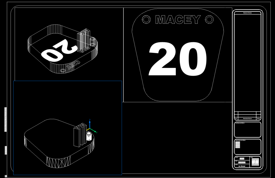
Ok I used Txtexp on "MACEY", then went to a 3d view so could see what was going on VPOINT -1,-1,-1. You have to check that all the objects that appear are plines I had to join the little "A" triangle. Ok extruded the base 1.5 Extruded the circles 2.5, then unionid both, to base, subtracted the inner circle from the new solid. Extruded the ""M" 4.5 then did a union again. Extruded the two parts of the "A" unioned together with base then subtracted the inner triangle, You can see the progress. What you want is not a single step but rather multiple steps, lastly can export the STL file. Once you get the hang of extruding, subtrcat and union you can do multiple objects at one time. This is a bit rough as a solid and can be done better, by moving the text to a Z matching base height before you start.
- Yesterday
-
LISP CODE INSERTING ELEVATION FROM CIVIL 3D SURFACE TO 3DPOLYLINES
BIGAL replied to darshjalal's topic in AutoLISP, Visual LISP & DCL
Why not just use the inbuilt "FEATUREELEVSFROMSURF " -
Having some issues converting to 3d
TimC replied to TimC's topic in AutoCAD 3D Modelling & Rendering
Sorry it took so long to get back. I never got notifications that there were any replies. OK, so maybe I'm missing something here and ChatGPT and Gemini are of zero help so far. I have this drawing. I'm trying to make a 3d printed ATV number plate. Extrude absolutely won't work for me, not sure why. I was able to use the "presspull" command to punch out the holes (which I don't believe is the correct way) and I can raise the plate up the 3mm I want and the support around the holes the additional 1mm I want but it absolutely won't do anything with the text. I tried MTEXT and single line text. Neither works My printer is a FlashForge AD5X Mark Macey Rear Plate.dwg -
 MSHR joined the community
 -
Automatically placing borehole tables with leaders without overlap
MSHR posted a topic in AutoLISP, Visual LISP & DCL
Hi everyone, I’m working on a complex borehole location drawing in AutoCAD with many boreholes and corresponding data tables. When a new borehole is added, I would like to have an AutoLISP routine that can automatically place a new table and leader for that borehole without overlapping the existing tables. The layout concept is roughly like the attached image: Each borehole is a point/block near the center of the drawing. Each borehole has a data table placed outside the central cluster. A leader (polyline or multileader) connects the borehole to its table, using straight segments and preferably angles that are multiples of 60 degrees (or similar fixed angles). When space on one side is not available, the routine should try other directions until it finds a free spot between the existing tables. What I would like the routine to do is: Take the new borehole (block or point) as input. Use a standard table block (or AutoCAD table) with a known size and insertion point. Search along several radial directions (0°, 60°, 120°, 180°, 240°, 300° or similar) at a given distance to find a position where the table’s bounding box does not overlap existing tables or a central “no‑go” area. Insert the new table at the first (or best) free position and draw the leader from the borehole to the table with clean, orthogonal/60° segments. I have some AutoLISP experience and I’m thinking about using: Block/table bounding boxes (vla-getBoundingBox) for collision checks. Simple rectangle overlap tests to avoid collisions. Polar coordinates for candidate positions at fixed angles and distances. Before I start building this “placement engine” from scratch, I’d really like your feedback: Has anyone already written something similar (automatic table/label placement around a central cluster, avoiding overlaps)? From your experience, is this approach (block + attributes + leader + bounding‑box collision tests) reasonable, or is there a better pattern? Any tips on robust overlap detection or examples of similar LISP routines you recommend looking at? Would you implement this with standard tables, block attributes, or something else for the borehole information ? Any ideas, sample code, or links to existing routines would be greatly appreciated. Thanks in advance for your time and suggestions! ** Find attached plz 11.pdf -
LISP CODE INSERTING ELEVATION FROM CIVIL 3D SURFACE TO 3DPOLYLINES
darshjalal posted a topic in AutoLISP, Visual LISP & DCL
3PS.LSP -
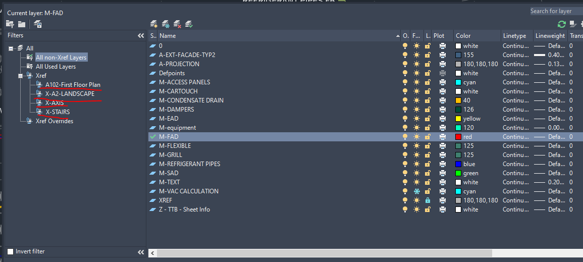
Hi Again for example, here I have 4 xref attached, I need to change the layers properties (make color 180,180,180 and line weight =default) for these xrefs without opening all drawings. Thank you for your time
-
 jalalmahmoud joined the community
 -
Set Pline Z value by selecting text
darshjalal replied to PaulyPHI's topic in AutoLISP, Visual LISP & DCL
PETA-INSERT ELEVATIONS FROM TEXTS INSIDE THE CLOSED OR OPEN POLYINE.LSP Try this one too - Last week
-
 Nymex joined the community
 -
 aepsmith89 joined the community
 -
@ababs "actually we attach the architectural drawings as xref " so why not do the changes then as part of an custom attach xref lisp. Again need an idea of what the layer names are and the relevant changes. How do you propose to identify the layers ? By wildcards "wall*" etc Were I worked we redid the color of layers by wildcards about 7 of them. So maybe 50 layers.