Search the Community
Showing results for tags 'corridor'.
Found 15 results
-

Slope pattern corridor, missing in alignment curves... Frustrating!!
Mark_CV3D posted a topic in Civil 3D & LDD
Hello, im having Civil 3d 2014 and having some problems with slope patterns. They are gone in corridor curves. Does anyone have any solution on this one? Heres a link to the file on sprend (it was too big for uploading here, 1,5mb): http://sprend.com/download.htm?C=1b28498e0a8f4d989b4ac9b7fabc660e best regards from a swedish frustrated cad user. -
Hi! I am trying to display all the elements from my subassemblies on the plan view. Can't find option responsible for display a bench from the subassembly called daylightbasin. I have a linework in a corridor showing bottom of the ditch, external side of a bench and link to surface, but all the options responsible for the bench seems to not working. Ideally I would like to add a feature line in all the places where my corridor change the shape, according to the created assembly, but really I have tried everything what I do know and it's just not working. I know I could do it manually, but I think that's not the purpose of using software like Civil 3D. As you can see in the last image, corridor line (external edge of a bench) is going in a bit different direction than the countours from the surface generated based on the corridor. Please help! It
-
Hello all, I am laying out a soldier pile wall and am having an issue with creating a top of wall profile. The piles are equally spaced and vary in height based on eg conditions. Does anyone know a way to have a vertical segment in a profile? My goal is to have my wall corridor have vertical steps when viewing and creating views and avoid having those little 'sloped sections'. Any help or suggestions are appreciated. thanks, phil
-
Hello all, I would like to know if anyone has been able to do the following: - create a corridor leaving all 'CreateCorridor' - 'Assembly Insertion Defaults' to the default values in the settings tab. -apply a different "style" that changes all the increment values. I'm trying to find a way to make custom corridor styles so users do not have to go in and manually change all the 25' increments to 50' (for example). They want to apply a 25' style and then change that to a 50' style at will. Any and all help is appreciated. thanks, phil
-
Hello, At the request of a co-worker I am trying to generate a table with the station number and % grade of the lane subassembly at that station. Any help is appreciated. Additionally, they want it to be a live, dynamic table in the drawing, not a toolbox report dropped into excel. Thanks! Phil
-
Is it possible? I have a colleague who uses InRoads. (I'll use C3D language here. . . ) He is able to select an assembly (in a corridor) based on input in an Excel spreadsheet. Is there anyway to import corridor Start and End stations? Is there anyway to dictate a region's assembly based on Excel data (even a copy/paste solution)?
-
Problem: We developed a proposed surface and generated contours from a 3D Corridor. The spot elevation labels were added along the corridor in each sheet file. When some of the spot elevations were changed, and some minor profile adjustments were made to the base line, the elevations on all the sheets changed. Many of these elevations no longer make sense (i.e. it now displays "???" or "-0.08" instead of "12.58"). What happened and how to fix?? Help!
-
I have built a corridor and corridor surface but I have a bowtie area (see attached pic) in the green circle. Can anyone give me a step by step on how to fix this? I tried removing the daylights in that area, but it still doesnt look right. I'm not so familiar with grading tools/groups so any help in that department would be appreciated. pics.docx
-
Codes missing when creating surface from datum of corridor
Mark_CV3D posted a topic in Civil 3D & LDD
Hello. My problem occurs when i have this railway assembly and want to create a surface from its bottom, (called "Datum" in english?). I have given the link at the bottom of the subbase the Code "Terrass" but it doesnt even show up when im in "corridor surfaces"-->add data--Specify code. None of the codes of the subbase shows up. What is wrong here? Im using civil 3d 2013 -
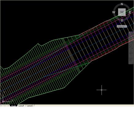
Hello Everyone, I am currently modeling a roadway using a proposed profile and assembly with daylighting cut/fill to an exising surface. The corridor seems to build fine with all feature lines and proper shading indicating areas or cut/fill daylighting but once I create a surface out of the corridor the surface boundarys for the most part will follow the extents of the outer boundary (both by using the corridor extents as outerboundary and using a polyline in the same way) but there are locations where the surface does not build causing the outer boundary of the surface to enter the corridor and follow the edge of pavement instead of where the daylighting meets the ground. the bluish green lines which intersect the corridor lines are the outer boundary of the surface created from the corridor. Anyone have any idea how to fix this? Thanks -mraymer

-
I'm trying to design a junction without using the Wizard. I can generate all of the necessary baselines/regions and target the Curb Return assemblies to a Feature Line generated along the carriageway edge of the Primary Road. What I can't work out is how to vertically attach the Curb Return kerbline profiles to the Primary Road corridor such that if and when I redesign the Primary road, the Curb Return kerblines dynamically update their level too.
-
Hello all, How can I create a smooth transition between subassemblies with different daylight slopes? I have a corridor with 2 subassemblies used. I set the regions up so type 1 is from Sta. 0+0 to 0+100, type 2 from 0+100 to 0+125, and then from 0+125 to end is type 1 again. The daylight slope for type 1 is 1.5:1 and it is 100:1 for type 2. Thanks in advance, Kyle
-
I've got an assembly of a crown road and daylight sloping running along a corridor. At one point there is a retaining wall along the shoulder which I want to daylight to (the rest of the road daylights to the original ground). I've inserted a "LinkOffsetandSlope" subassembly that will do what I want in the area of the wall (represented by a feature line). But for areas of the road where there is no wall, it still shows a link running to the default offset. Is there any way I can make this work without making another assembly and separate region? Thanks...
-
I'm working on a road project that is 3 lane road. a northbound, southbound and center turn lane. At an intersection it changes into having a left turn lane only with a median. So my problem is that when I have multiple regions in my corridor with and offset assembly targeting a offset alignment the last (or first depending ion which side the offset is on) set of links between the sample lines on the offset side of the assembly go missing. I've built the assemblies multiple ways and built it using different baselines and the same problem keeps coming up....I'm lost on it. Any ideas?
-
Greetings all! I have a dilemma that I thought sounded pretty straightforward, but have discovered it is not. I have a levee for a project involving wetlands and each levee has an alignment, profile and corridor associated with it. My problem is that I have different sideslopes along the levee you see. I have places where the side slopes are 10:1 and then go to a 4:1 and THAT is where my problem and question is. I have an assembly with a 10:1 slope, I have an assembly with a 4:1 slope; how do I properly make the transition between the two assemblies inside of my corridor? Here is what I have done thus far: I created an additional assembly that had just the levee top. I broke the corridor into 3 regions and thought that if I had a region with the 10:1 assembly, a region with the levee top only assembly, and then the 4:1 assembly the corridor would transition the daylights between the two, but alas it does not. Any help, or suggestions would be greatly appriciated. Thank you for reading. Sincerely, Mike