Search the Community
Showing results for tags 'parametric'.
Found 8 results
-
 Hello Everyone, I am trying to align simple objects (line circles, etc) and blocks to lines that exist in a xref'd file. An example is if I have a general arrangement floor plan (that has been produced and owned by others in my team). I would like to create a set of dynamic drawings that would change with changes to the general arrangement drawing. I understand that the original author can add, delete and redraw lines that I have aligned to, however I will address these as they occur.
 -

Applying attributes to dynamic block & extracting to table
claire2017 posted a topic in AutoCAD Drawing Management & Output
Hi All, I'm very new to these so please be nice! Basically our company cuts heaps of metal panels. We draw each panel, do the cutting lists, nest and optimise them on sheets manually. I'm trying to save some time by creating a block that'll make life a bit easier. So I've currently got a block where you can input the height and width & it automatically adjusts. What I'd like to add is an atrribute? or a tag? where that little box pops up and you can input the height & width in there instead. Additionally I'd like the pop up box to include the panel # which is then shown on the panel (see drawing where I've just added in 'a1', 'a2' etc). Next step would be to include a table that collates the information from all the panels (we often do around 30 panels per order). Currently we manually input all the sizes in to excel. Just to make things more interesting we use metric autocad but are often given dimensions in imperial, so half the time is spent manually converting feet & inches into mm and then drawing the panels in mm. If there's any way to input in imperial and show both metric and imperial on the dimension line that would just be the best thing ever! I might be being a bit greedy with so many requests so if anyone could help with just one of the above it would be very much appreciated. Thankyou trial.dwg -
Check out this new Engineering & CAD automation service. AutoEngr.com. Our services include CAD API programming and parametric modeling services for zero up-front costs. We create custom automation to match you needs, then run it whenever you need to complete the task. It's a hassle free low cost solution to automation. Request a custom service or use an existing off-the-shelf service today!
-
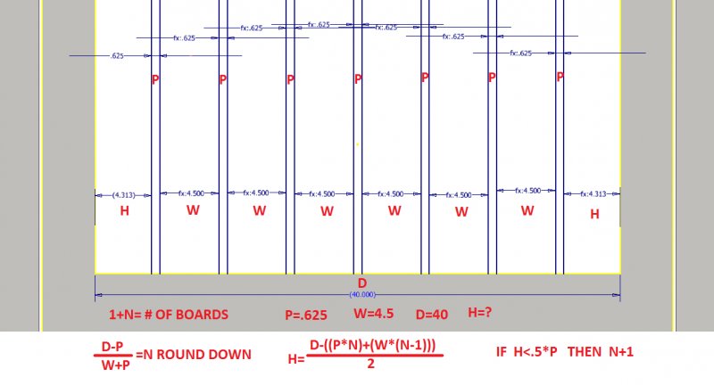
I searched but could not find a good answer so I thought I would give you all something fun to play with. I am trying to space a gate formula where the pickets and wood slats are computed based off the lengthening of the gate. I figured the formula and it seems to be what I need but now implementing it into Inventor is where I fail. The problem is if the gate gets too big it won't fill in the huge spaces on the sides. Attached is an image of what I'm trying to do and the formula I put together. This would save me time and headache of having to figure it out every time and make the model parametric. I typically work with iProperty forms to drive my model, but haven't had much need for Rules or iLogic or iParts. Usually just Vault copy design, scaling the door frame width & height then changing out components and adding detail works quickly and efficiently. With gates however, they are all long runs of pickets and spacing by Rules would be perfect. Thanks!

-

Dynamic blocks and dimensional constraints
DRBJR45 posted a topic in AutoCAD Drawing Management & Output
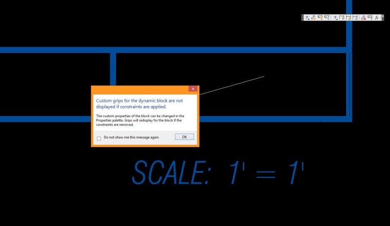
Hello all, In the attached file there is a dynamic block, the blue box. In the lower right corner there is text showing the scale of the viewport that is inside the box. The text contains a field that will update to show the scale of the viewport automatically when the viewport scale is changed. Here's my problem, I need the text to remain at the lower right corner of the box during the stretching of the dynamic block. I've tried using dimensional constraints but this caused the dynamic block to stop working, it wont stretch. I need help please! Thanks DRBJR45 DYNAMIC BLOCK QUESTION.dwg
-

Stress Analysis: Use outputs from stress analysis for defining input parameters
petedow posted a topic in Autodesk Inventor
Is it possible to take outputs from the stress analysis such as reaction moments around fixed constraint and to define these as a parameter on input to other parts of inventor. e.g. the force in the downwards direction around a bolt hole modelled as a fixed reaction is 200N. Can you then use this value and input it into a bolt calculator automatically? To avoid having to redo this everytime the model changes? -

Creating custom duct fittings as MV Part, What do you think? and some more questions!
cancer24 posted a topic in MEP
Hello everyone, I have some questions... I know that custom duct/pipe fittings have to be created as parametric parts, not MV parts. But from my humble experience of spending more than 48 hours trying to create a rectangular concentric Y branch duct fitting, I say no more messing with the AMEP parametric part builder! The user interface is too difficult, (I mean come on, I can't even use the UNDO command (Ctrl + Z)... What to to expect! I remember long time ago, creating HVAC equipment using the MV part method, was a piece of cake for me.... But I hear that this method should not be used to create fittings (duct/pipes etc) .... It's only for equipment! Are there disadvantages for that? Is there, somewhere... or someone, who has a collection of duct fittings to be used with AMEP.. I mean that which are created as parametric parts... I wonder if you guys would feel okay sharing with us what you have, just like the old days when we shared Autocad blocks and details! That's it for now, Thanks in advance. -

I have a little Problem with Parametric Area
dglopes posted a topic in AutoCAD 2D Drafting, Object Properties & Interface
Hi, Im trying to do a polygon with a parametric constraint, the Area. How can i maintain the same area with differents side values? The polygon is the Trapeze. The dimensions are: 54 (biggest side) 28 (small side) ~23 height Tks a lot