Search the Community
Showing results for tags 'view'.
Found 24 results
-

Multiple Paper Space Layouts, Multiple Views and only One ViewPort in VB.NET
turkish posted a topic in .NET, ObjectARX & VBA
Hello to everybody, I'm writing my first message as I started developing my first App. The thing is I have a dwg with the same number of paper space layouts and views, and the same viewport for all the paper space's layouts. So the problem is: I'm stuck trying to link the viewport of each layout to the correspondig view. I attach in .txt the code for VB.NET and appreciate if anybody can help me in this very first real project. Thanks for helping.CODES.txt -
Hello, I've been asked to make facade views from a survey in 3D. I have the house in 3d lines and i would like to extract the front-, left-, right- & back view of the facade. i used to do this by redrawing in an other file, but there has to be an easy way to "extract" that view. 1245337672_3dhouse.dxf
-
I'm trying to modify some code to achieve the following: Ask the user to pick multiple blocks, step through each block, get the extents of the block, and save a view with the view name equal to the name of the block. Doing some research I've managed to get the extents of the block but can't figure out how to store the block name as a variable and use it as the view name. The code I found will draw a rectangle around the block using vla-getboundingbox but I can't figure out how to assign the name of the block to a variable for use in the -view command. I have a few hundred blocks in the same drawing. Existing code is: (defun c:BlockExtentsToRectangle (/ BlockObject mn mx) (vl-load-com) (if (setq BlockObject (car (entsel "\n >> Select Object >> "))) (progn (vla-getboundingbox (vlax-ename->vla-object BlockObject) 'mn 'mx) (vl-cmdf "._rectang" (vlax-safearray->list mn) (vlax-safearray->list mx)))) (princ) )
-
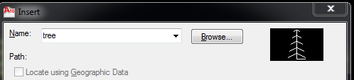
Hello, i try to insert block view in dcl format. I want when i chose block name to have block view to. Something like this.

-

Lisp to create and name layouts and restore views by reading excel or notepad file?
bkirtland posted a topic in AutoLISP, Visual LISP & DCL
Hi everyone, I'm new to using macros/lisps in AutoCAD, though I do have a small programming background in some other programs. To give you some background on what I'm trying to do: I have a big .dwg file that shows all of the roads in a particular city in the USA, and I have created views of all of the intersections that have crosswalks. All of these intersections have their own intersection IDs, which have a format such as BRI1, BRI2A, BRI3B, BRI4, BRI5, etc., through BRI170. I have already created all of the views from these intersections, and now, in the same .dwg, I am trying to quickly create layouts from a template that show only one view each. I have a .dwt set up for this, and the name of the layout for this template is EB124. I want the layout tabs to be named corresponding to an intersection ID, and then have the viewport show that same view. So, I want layout 1 to be renamed BRI1, and have the viewport view restored to the named view BRI1, and so on for all of the named views. Here are the commands that I used to create a macro for this using the Action Recorder: -layout > t > [select template from file] > EB124 -layout > set > EB124 -layout > rename > EB124 > [ASK FOR USER INPUT, example BRI1] [select the viewport in the new layout and unlock the display] MSPACE -view > restore > [ASK FOR USER INPUT, example BRI1] PSPACE [select the viewport and lock the display] This macro works great, except that I have to press play and enter the intersection ID twice per layout tab. I'm wondering if its possible to create a lisp that does this routine but reads an excel (or other) file and loops through and creates all the layout tabs in one fell swoop? Thanks in advance for all of your help! -

How to draw side view knowing only top and front view?
khoshravan posted a topic in AutoCAD 2D Drafting, Object Properties & Interface
My question is not related to CAD directly, however some of you may help to get a proper answer. It is about drawing 3 views of an object. My daughter is a 1st semester student in Mechanical Engineering dept. She has drawing course. She asks me to help her with following problem. Two views from three views (top-front- side) of an object is given. She has to draw the 3rd view without knowing the perspective of the object. She knows the basics but mess up when the question becomes hard. What is your comments for helping her to master imagination techniques? Is there any downloadable book in this regard? I have heard about a software which helps with mastering this techniques but a search in Google was not helpful. -
Hello, I want to be able to add a profile view label that will label the station and profile elevation by entering the station and having the label 'extract' the elevation from a selected profile. The inquiry tool will report the elevation but that's not what I require. I have also been unsuccessful in creating an expression that will do this. To sum it up, I want to add a profile view station and elevation label by selecting or entering the station and then selecting/picking the design profile. Any and all help is appreciated. thanks, phil
-
Hi to everyone!... Someone knows a Lisp to plot a internal sheets of a model space file? Eg.: I have a dwg file with 10 sheets internal, I know how to put name at each sheet (NEWVIEW) and it appears at same place of Extend, Display or Window at plot configuration screen. If I put names as a numbers: 1, 2, 3,..., 10, it's possible to select one page or all to plot at the same time? Or create a Lisp that can help it!?... Thanks in advance!... Its possible using a comand: -plot Detailed plot configuration? [Yes/No] : y Enter a layout name or [?] : Enter an output device name or [?] : Canon iR2525 Enter paper size or [?] : Enter paper units [inches/Millimeters] : m Enter drawing orientation [Portrait/Landscape] : Plot upside down? [Yes/No] : Enter plot area [Display/Extents/Limits/View/Window] : v Enter view name : 3 (the view name) Enter plot scale (Plotted Millimeters=Drawing Units) or [Fit] : Enter plot offset (x,y) or : c Plot with plot styles? [Yes/No] : Enter plot style table name or [?] (enter . for none) : Plot with lineweights? [Yes/No] : Enter shade plot setting [As displayed/legacy Wireframe/legacy Hidden/Visual styles/Rendered] : Write the plot to a file [Yes/No] : Save changes to page setup [Yes/No]? Proceed with plot [Yes/No] :
-
I looked for a way to create a detail and arrived to Layout tab, Crate View, and Detail. But at Create View, Detail is dimmed, non clickable. Can someone help? Thanks, Luis.
-
I have some macros that will set the view to 0,0 once completed out of nowhere. Some of these are macros that I've used for some time with no problem. All "View change" commands within the macros were deleted when created (if needed) and all options in the actmanager under "Restore pre-playback view" are unchecked. It seems to only do this when using a macro involving calling a block. Any idears?? Thanks, -Nobull
-
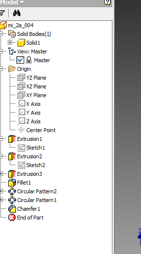
Hi, I'm pretty new to inventor and I need help. So right now I'm trying to follow what Mastering Autodesk Inventor 2015 says and one of the steps(#5 pg. 53) shown is ambiguous to me.I don't see any dotted line view and the only view I see is the master view which I cannot delete. If not that, I would also like help on trying to place a view.Thanks! "Step:5 Right-click the dotted view border and choose Delete; then click the OK button to confirm that you want to delete the view."
-

Calculate the Dip (angle) of a 3D Polyline
toxicsquall posted a topic in AutoLISP, Visual LISP & DCL
Hi, I would like to know: are there any lisp that can calculate the DIP and the length of a 3d Polyline, in Front View or any other view? -
Hi, I've used autocad 2007 and recently change to autocad 2014. My problem is in 2014, when I want to work with front view, the ucs doesn't change with it. It stays with the top view. I've typed ucs>"V">enter and it changes the ucs along with my view from front to top. I want it to be it still in the front view, and the ucs will show x and y normally. Please help, thanks in advance *In autocad 2007, when I change view, the ucs automatically change as well following the view.
-
I have created a view to zoom to my titleblock and plot stamp so that I may check revision dates. I then put this to a macro for easy access to the view (I keep the ribbon closed for maximum screen size most of the time). It seems that these saved views are only saved in the current drawing and I would need to save a view for each drawing file. This can be cumbersome for many drawings. Is there an easier way to view a certain area in paperspace? Or is there a lisp out there to create a saved view in multiple drawing files? Thanks for your time, -Nobull P.S. I also just realized this saved view not only goes to certain position but also switches to that specific layout. Is there a way to just save a position in paperspace to use on any layout?
-
Afternoon All, I'm working on a project that requires me to produce phasing drawings for store alterations at a well known supermarket. I have a LIVE plan which is the existing floor plan and a FOS plan which is the proposed; I move/copy from the proposed into the existing detailing the changes needing to happen this involves lots on layers and a shed load on layer states. I work with two viewports in Model spaces one showing the existing the other showing the proposed. At the moment I scroll around the store in one VP then have to move to the same spot in the other. I was wondering if there is a way to 'link' the two viewports so that as I scroll around in one the same spot all be it on the other plan shows in the other viewport. I currently keep the two drawings about 100000mm apart so any moves or copies are an easy number. Look forward to hearing your thoughts Stenna
-
Hi everyone, I have experience making 3D models in Vectorworks but have never used 3D in AutoCAD. I am using 2014 version. I understand the principle of UCS and the idea behind it but am really struggling to use it. Currently I am trying to use two viewports, one in top view and one in front view. I am trying to use the two to ensure I am placing objects in the correct place in relation to everything else. However...how comes when I move something up or down in front view it moves completely out of position in top view? surely if i'm moving the object up or down it should not effect the position of anything in top view? Many Thanks
-

Unable to view items as i draw
cbgcm posted a topic in AutoCAD 2D Drafting, Object Properties & Interface
For some strange reason when I got to work this morning I was unable to view items as I draw. I can see lines as I draw once I specify the first point with ortho on or off, but I can't see shapes (dimensions, circles, rectangles, ellipse, or box) while I draw. Once I select the second point the object does appear but a setting has changed and I can't figure out how to get it back to normal. Any help would be greatly appreciated. -
Hi, I am looking for an explanation why when the view cube and the view control do not harmonize. When I set the view to front to start a 3D model, the view cube is set to Top. When I change the viewcube to Front, the view has automatically been set to Bottom. Is this a bug or something I am missing? Also drawing a front view. Is is ok to just turn the view to Front and start drawing on the same XY plane? Or I also need to rotate the UCS to ZX? Does such initial position important with respect to future rendering? Thanks.
-

Tool pallette images - why are some too small ?
vickilb posted a topic in AutoCAD Drawing Management & Output
Morning Folks, Got a slightly irritating little niggle with tool pallettes, that i was rather hoping that some clever soul on here might have the answer too. I have just updated a whole load of block symbols as some numpty didnt put them on layer 0. When i have created a tool pallette of the sysmbols, 4 of approx 30 symbols have got such a tiny tool image, that its impossible to see them, but oddly the rest are fine. I have checked the blocks are zoomed to extents, checked the drawing limits are the same ones that are okay, and checked that the size of the block is the same, effectively i can not see any diference between the blocks. Even when i increase the image size to max in the tool pallette view options the symbol is to small to identify. Oddly in windows explorer and in ACAD design centre there is no issue with the tool image size. Whilst i could manually create a new image, and tell the tool pallete to use it, if this happens with all the blocks, it could be time consuming, when there could be a very simple answer i have over looked. Cheers in advance for any suggestions of no doubt whatever simple thing i have missed Vicki (still stuck on ACAD 2008) -
Hi everyone, I want to change a helix to a 2d object as shown in current view (the current view isn't necessarily plan view or front view, etc.) Any suggestions is greatly appreciated
-
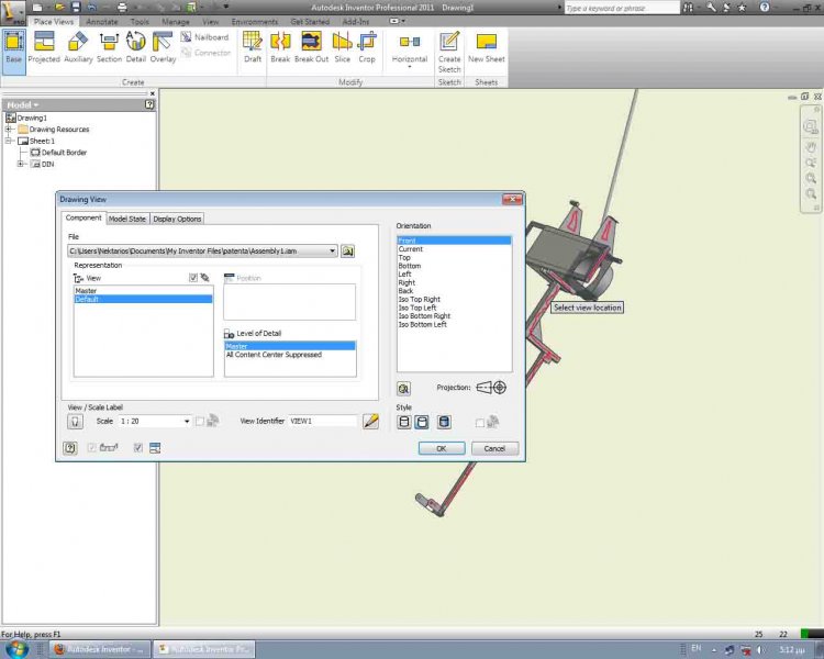
I am new in Inventor. I created a simple model. Then i tried to get a drawing of it. I can't get the axes orientation right. The model CreateDrawing Environment is rotated and i can't get it right in view. I mean when i create a base view , whatever view i choose the model looks rotated in the view. As you see from the picture that's not a "front view". I expect the "front view" to show me the model colored in red, nicely horizontal. How can i point to Inventor which view is what ? In CreateAssembly environment the model in "Home View" looks weird rotated too. I assume the problem starts from the CreateAssembly procedure, though i am not sure. Anyway, what can i do to fix that ? Thank you for your help.
-

What do I do to turn wire framed solids into solids
cyter posted a topic in AutoCAD 3D Modelling & Rendering
Like when I draw a cylinder, instead of a solid cylinder I get two circles joined by two lines. How do I change this so that I get the solid? -
Hi, i'm wondering how to get orthographic views isometric view (with some dimentions) from an object ive already assembled with proengineer (student). Would be nice if somebody could point me in the right direction. Thanks
-
I am using AutoCAD 2007 with Windows XP in Sony Laptop. When I start AutoCAD, it shows the 3D view with gray background and xyz ucs in color. I am used to 2D view with black background. However I don't know how to change and make this permanent, so that every time I open AutoCAD it opens the 2D black and white view. I have tried view/3D views/Plan View, but it doesn't help