Search the Community
Showing results for tags 'dim'.
Found 6 results
-
 I would like some help to create a function that would allow me to select a point in between two horizontal and/or vertical lines and it would give me the vertical and horizontal dimensions between those lines. It's a 2D drawing but some lines are of different z value. I have tried using chatgpt to create a code but it is not able to properly select the nearest line from my specified point (after running the command). This function is there in the new sketchup. I was hoping to use it to create internal dimensions in an architectural plan.
 -

Set MLeader to Existing MLeader Style via LISP
parkerdepriest posted a topic in AutoLISP, Visual LISP & DCL
Hello, I am trying to create a lisp routine that sets all existing MLEADERs to a certain pre-set MLEADERSTYLE, the equivalent of doing a Quick Select for Mleaders, and setting the style under the properties window. I was able to write a similar routine that selects all dimensions and sets them to a certain DIMSTYLE, using entmod and DXF code 3 for dimstyle. So far, I have not been able to find a group code for MLEADERSTYLE Any help would be greatly appreciated! (defun C:dimstylechange (/ ENTITIES NO_OF_ENTITIES SSPOSITION ENTITY_NAME OLD_ENTLIST NEW_STYLE NEW_ENTLIST) (setvar "CMDECHO" 0) (setq ENTITIES (ssget "X" '((0 . "DIMENSION")))) (setq NO_OF_ENTITIES (sslength ENTITIES)) (setq SSPOSITION 0) (repeat NO_OF_ENTITIES ;***CHANGE STYLE*** (setq ENTITY_NAME (ssname ENTITIES SSPOSITION)) (setq OLD_ENTLIST (entget ENTITY_NAME)) (setq OLD_STYLE (assoc 3 OLD_ENTLIST)) (setq NEW_STYLE (cons 3 "BCR 11x17")) (setq NEW_ENTLIST (subst NEW_STYLE OLD_STYLE OLD_ENTLIST)) (entmod NEW_ENTLIST) ;***CHANGE LAYER*** (setq OLD_ENTLIST (entget ENTITY_NAME)) (setq OLD_STYLE (assoc 8 OLD_ENTLIST)) (setq NEW_STYLE (cons 8 "DIM")) (setq NEW_ENTLIST (subst NEW_STYLE OLD_STYLE OLD_ENTLIST)) (entmod NEW_ENTLIST) (setq SSPOSITION (1+ SSPOSITION)) ) (command ".CHPROP" ENTITIES "" "C" "BYLAYER" "LT" "BYLAYER" "") (princ (strcat "\n..." (rtos NO_OF_ENTITIES 2 0) " Dimension(s) changed...")) (setvar "CMDECHO" 1) (princ) ) dimstylechange.LSP -

Replace Block with Centermark Problem Solving Question....
ILoveMadoka posted a topic in AutoLISP, Visual LISP & DCL
I create drawings from Solidworks and bring them into Autocad all day. The centermarks come in as blocks all with unique names. Our drafting standard requires me to delete these center marks.. (I think Lee or someone coded a cool routine that did that for me..) (Lee or someone also wrote a snippet of code that allowed me to select a group of circles and have a centermark placed in each per the current DIMCEN settings.) I was going to attempt some code that automated all that into one routine. I hit a snag when I realized I can't "replace" the block with a standard centermark since placing a centermark requires selecting a circle. I could create a block and replace the block but we have so many varying scales plus our "standard" centermark is not a block so I'd be outside the drafting standard by doing that. I was thinking along the lines of drawing a circle at the block insertion point, then placing a centermark there then deleting the circle. Since there are people here much smarter than me in problem solving I'm asking if this would be the way to go of does someone have a better suggestion? Here is my code where I stopped when I realized I had to pick a circle. It's not much I know... (defun C:SWC (/ I SS) (Prompt "Replace SW Centermark with DIMCEN:") (setq SS (ssget "x" '((0 . "INSERT")(2 . "*SW_CENTERMARKSYMBOL_*")))) (setq I 0) (command ".dim") (repeat (sslength SS) (command "center" (list (ssname SS I) '(0 0))) ;!!!It wants a circle to place the centermark in! Draw & Erase? (setq i (1+ I))) (command "exit") ) (command "Erase" SS "") (princ)) Thanks ... -

Cannot rotate dimension text to desired angle
jdavid10 posted a topic in AutoCAD 2D Drafting, Object Properties & Interface
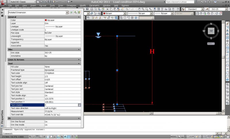
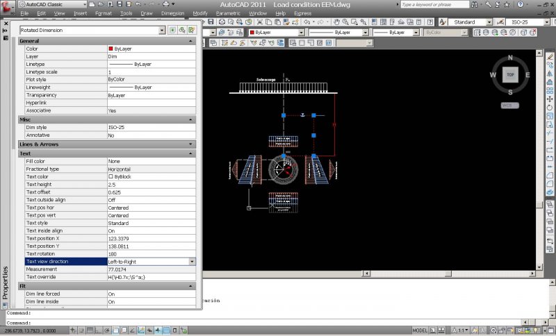
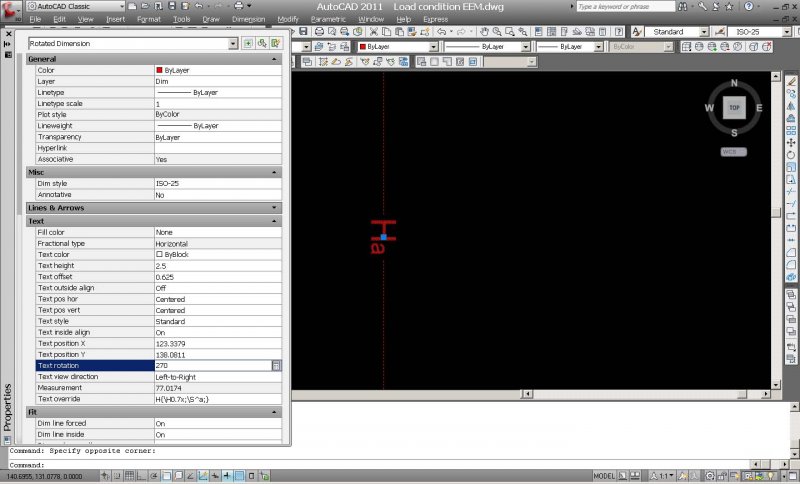
Hello everyone, I'm making this diagram of the load condition acting on tunnels to explain a Japanese set of equations that are used for the structural analysis for tunnels: But, there is one problem I have. I'm trying to set up the text for the dimension between the water table and the tunnel "Ha" to look horizontal. However, if I click on the properties box and write 90 in the rotation box right next to where it says "text rotation," the dimension text does not rotate 90 degrees; if instead I try to rotate it 180° then it only rotates 90° (and in the opposite direction) instead of 180°. It doesn't matter how many degrees I choose, it won't rotate my dimension "Ha" to desired angle to make it look horizontal. OK I know it's hard to explain my problem with just writing, so I've posted a few pictures: In this one, the dimension is at 0°; I've only opened the properties box to attempt and rotate it: Now I write 90 in properties box but the dimension text does not rotate at all; it remains at 0 as it is shown in the following image: Next I try to rotate 180, just to see what happens; and it does rotate (only 90 degrees!): I finally try to rotate the text 270 just to see if it rotates to desired angle and it does rotate (180 degrees from original position). As shown below: It doesn't matter how many degrees I choose, I cannot make it look horizontal. Is AutoCAD wrong? Or am I wrong? lol xD Any ideas? I'm about to loose a quarter pound of my hair from just thinking about this. Lol just kidding but this is very annoying. How can I set up my dimension text "Ha" to look horizontal? Please help.
-
Hello Now that the problem with OS, XP, W7, 16bit, ... is solved with this little lisproutine, which I'm very happy for it, I discover another small limitation. I noticed that it only measures arc's and no lines. Is it possible to fix this problem? It would be great if it also can measures lines (at the same time time) Does anybody can help me with? Thx in advance Gr ARCRLVOOR_DimVoorSnijden.lsp
-
Hi guys I just had an upgrade of Autocad 2010 to 2013. However, a very important lisproutine doesn't work properly anymore. What has happened? Can someone help me please? With the lisp I can select several arcs (not polylines!) and when I enter the length and the radius appeares above the selected lines. ARCRLVOOR_DimVoorSnijden.lsp Thx.