Search the Community
Showing results for tags 'arc'.
-

Distance Command Leaves Arc Shaped Residue
"Mitch" posted a topic in AutoCAD 2D Drafting, Object Properties & Interface
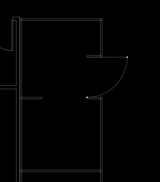
Lately, maybe about a year, I've noticed a residue of an arc shape (perpendicular to first and second point within distance command). I tried Regen, Regen All and Redraw. Any of them clears up the arc residue for some and not others. Anyone seeing this arc image will think there's a door placed there. Anyone else here managed this issue? Image example attached.
-
Hello, i create lisp for transform *line, circle, arc ... and the question is: How to transform arc without convert it to polyline. Or how to covert arc to polyline transform vertex (this method work fine) and convert again to arc (i don't know how to convert again to arc). What i do, have a lot of math to coordinate system 1 --> coordinate system 2, when i covert vertex of lines everything work perfect but with arcs don't know how to transform vertex clear. This is about my dissertation. Thank you
-
Hello i need some help with modifying Arc, the idea to change coordinate with some formula like : Coordinate X + 100.00m for each point and coordinate Y + 200m for each point. For clear arc i decide first to modify center and then start and end point and it work, but for polyline with arc segment dont know what exactly to do. Thank you for help !
-
 I can't find a way to draw an arc off the end of a line or arc that is NOT the last entity and have it act as though it was continuing in the normal way, like it does when continuing off the end of the last entity drawn. As in, have it behave like an arc coming off the last entity but select a random different arc in the drawing. I always have to trace the arc or line that I want to continue off of, then use arc continue as normal. Tangent does not work because then you have to pick Center or End and then you're locked into an arc that is not behaving like a continuing arc. I hope this makes sense. I have a feeling it will be something like a small .lsp or .vlx program that moves the selected entity to the last item in the db dictionary, then I'd still have a 50/50 chance that it would be the correct end of the line or arc that I want. I know someone here knows how to do this! Thanks much, R.L. Hamm
 -

Convert polyline with arc to polyline with straight lines.
dunthy posted a topic in AutoLISP, Visual LISP & DCL
Hi all - I created a lightweight polyline by filleting two straight polylines to create 1 polyline that contains an arc. I would like to convert the arc into a series of straight polylines that mimic the original shape of the arc, while not disturbing the straight parts of the polyline. I found a .lsp routine that does this perfectly, but it only works for the older heavyweight polylines. Can anyone help modify this routine so it works for lightweight polylines or provide another suggestion? Id rather not convert to heavyweight, use the routine, and convert back to lightweight. Thanks so much! Here is the code: ;;;Translate plines w/ arcs to plines w/ mult. straight segments for use ;;;with DTM TIN's for contouring. Rounds out pline arcs via a suitable no. ;;;of straight segments. The determiner is based on small angle deflection. ;;; ;;; AUTHOR: HENRY C. FRANCIS ;;; 425 N. ASHE ST. ;;; SOUTHERN PINES, NC 28387 ;;; ;;; All rights reserved without prejudice. ;;; ;;; Copyright: 5-10-96 ;;; Edited: 10-1-98 ;;; (DEFUN c:plxl (/ found) (SETQ osmod (GETVAR "osmode") fltot 0 incrn 0 ) ;_ end of setq (SETVAR "osmode" 0) (SETQ usrdeg (ureal 1 "" "Deflection angle (< 5 degrees)" (IF usrdeg usrdeg 5.0 ) ;_ end of if ) ;_ end of ureal ) ;_ end of setq (SETQ usrrad (* (/ usrdeg 180.0000) PI)) (SETQ pliness (SSGET '((0 . "POLYLINE")))) (IF pliness (PROGN (COMMAND ".undo" "m") (SETQ plinesslen (SSLENGTH pliness) sscount 0 ) ;_ end of setq (WHILE (< sscount plinesslen) (SETQ currpline (SSNAME pliness sscount)) (SETQ plent (ENTGET currpline)) (SETQ plvert (ENTGET (ENTNEXT (CDAR plent)))) (PROGN (ENTMAKE (LIST (ASSOC 0 plent) (ASSOC 8 plent) (ASSOC 66 plent) (ASSOC 10 plent) (ASSOC 70 plvert) ) ;_ end of list ) ;_ end of entmake (ENTMAKE (LIST (ASSOC 0 plvert) (ASSOC 10 plvert) ) ;_ end of list ) ;_ end of entmake ;;;----repeat this until the end of the polyline (WHILE (/= (CDR (ASSOC 0 (ENTGET (ENTNEXT (CDAR plvert))))) "SEQEND" ) ;_ end of /= ;;;------if it begins an arc segment (IF (/= (CDR (ASSOC 42 plvert)) 0) ;;;--------do this (PROGN (SETQ found T) (SETQ plnvert (ENTGET (ENTNEXT (CDAR plvert)))) (SETQ strt40 (CDR (ASSOC 40 plvert))) (SETQ end41 (CDR (ASSOC 41 plvert))) (SETQ fpt1 (CDR (ASSOC 10 plvert))) (SETQ fpt2 (CDR (ASSOC 10 plnvert))) (SETQ chrdl (DISTANCE fpt1 fpt2)) (SETQ theta (ATAN (CDR (ASSOC 42 plvert)))) (SETQ psi (- (/ PI 2) (ABS theta))) (SETQ phi (* (ABS theta) 4)) (SETQ chang (ANGLE fpt1 fpt2)) (SETQ arcr (ABS (/ (* (DISTANCE fpt1 fpt2) (SIN psi)) (* 2 (COS theta) (SIN (* 2 theta))) ) ;_ end of / ) ;_ end of abs ) ;_ end of setq (SETQ arcc (IF (> theta 0) (POLAR fpt1 (+ (- chang theta) psi) arcr) (POLAR fpt1 (- (- chang theta) psi) arcr) ) ;_ end of if ) ;_ end of setq (SETQ fenl (* phi arcr) count (1+ (FIX (/ phi usrrad))) plwinc (/ (- strt40 end41) count) plwe (+ strt40 plwinc) incra (/ phi count) incrn 0 initang (ANGLE arcc fpt1) ) ;_ end of setq (WHILE (> count 0) (SETQ incrn (1+ incrn)) (SETQ plwb plwe plwe (- plwe plwinc) ) ;_ end of setq (IF (< theta 0) (SETQ fpt4 (POLAR arcc (- initang (* incrn incra)) arcr) ) ;_ end of setq (SETQ fpt4 (POLAR arcc (+ initang (* incrn incra)) arcr) ) ;_ end of setq ) ;_ end of if (PROGN (ENTMAKE (LIST (CONS 0 "VERTEX") (ASSOC 8 plvert) (CONS 10 fpt4) ) ;_ end of list ) ;_ end of entmake (GRDRAW fpt1 fpt4 -1) ) ;_ end of progn (SETQ fpt1 fpt4 count (1- count) ) ;_ end of setq ) ;_ end of while (SETQ plvert (ENTGET (ENTNEXT (CDAR plvert)))) ) ;_ end of progn ;;;--------or else it begins a line segment so do this (PROGN (SETQ fpt1 (CDR (ASSOC 10 plvert))) (SETQ fpt2 (CDR (ASSOC 10 (ENTGET (ENTNEXT (CDAR plvert))))) ) ;_ end of setq (SETQ fenl (DISTANCE fpt1 fpt2)) (ENTMAKE (LIST (CONS 0 "VERTEX") (ASSOC 8 plvert) (CONS 10 fpt2) ) ;_ end of list ) ;_ end of entmake (GRDRAW fpt1 fpt2 -1) (SETQ fpt1 fpt2) (SETQ plvert (ENTGET (ENTNEXT (CDAR plvert)))) ) ;_ end of progn ) ;_ end of if ) ;_ end of while (IF found (PROGN (ENTMAKE (LIST (CONS 0 "SEQEND") ) ;_ end of list ) ;_ end of entmake (ENTDEL currpline) ) ;_ end of progn (PROGN (ENTMAKE) (COMMAND ".redraw") (PRINC "\nPolyline contains no arcs. ") ) ;_ end of progn ) ;_ end of if ) ;_ end of progn (SETQ sscount (1+ sscount)) ) ;_ end of WHILE ) ;_ end of progn ) ;_ end of if (PRINC) ) ;_ end of defun ;|«Visual LISP© Format Options» (72 2 40 2 T "end of " 60 9 2 0 0 T T nil T) ***Don't add text below the comment!***|; I also had to add this into AutoCAD to get it to work: ;This function is freeware courtesy of the author's of "Inside AutoLisp" for rel. 10 published by New Riders Publications. This credit must accompany all copies of this function. ; ;* UREAL User interface real function ;* BIT (0 for none) and KWD key word ("" for none) are same as for INITGET. ;* MSG is the prompt string, to which a default real is added as <DEF> (nil ;* for none), and a : is added. ;* (defun ureal (bit kwd msg def / inp) (if def (setq msg (strcat "\n" msg " <" (rtos def 2) ">: ") bit (* 2 (fix (/ bit 2))) ) (setq msg (strcat "\n" msg ": ")) );if (initget bit kwd) (setq inp (getreal msg)) (if inp inp def) );defun ;* (princ) ;* -

select multiple polylines and convert straight to arc segments
jntm226 posted a topic in AutoLISP, Visual LISP & DCL
this lisp convert polyline segments to arcs . work one line for time . i need select 1000 polylines for times. I'm new in autolisp and i do know what change in the code : (defun c:lwsegs2arced ( / massoclst nthmassocsubst v^v unit _ilp doc lw enx gr enxb p1 p2 p3 b i n ) (vl-load-com) (defun massoclst ( key lst ) (if (assoc key lst) (cons (assoc key lst) (massoclst key (cdr (member (assoc key lst) lst))))) ) (defun nthmassocsubst ( n key value lst / k slst p j plst m tst pslst ) (setq k (length (setq slst (member (assoc key lst) lst)))) (setq p (- (length lst) k)) (setq j -1) (repeat p (setq plst (cons (nth (setq j (1+ j)) lst) plst)) ) (setq plst (reverse plst)) (setq j -1) (setq m -1) (repeat k (setq j (1+ j)) (if (equal (assoc key (member (nth j slst) slst)) (nth j slst) 1e-6) (setq m (1+ m)) ) (if (and (not tst) (= n m)) (setq pslst (cons (cons key value) pslst) tst t) (setq pslst (cons (nth j slst) pslst)) ) ) (setq pslst (reverse pslst)) (append plst pslst) ) (defun v^v ( u v ) (mapcar '(lambda ( s1 s2 a b ) (+ ((eval s1) (* (nth a u) (nth b v))) ((eval s2) (* (nth a v) (nth b u))))) '(+ - +) '(- + -) '(1 0 0) '(2 2 1)) ) (defun unit ( v ) (mapcar '(lambda ( x ) (/ x (distance '(0.0 0.0 0.0) v))) v) ) (defun _ilp ( p1 p2 o nor / p1p p2p op tp pp p ) (if (not (equal (v^v nor (unit (mapcar '- p2 p1))) '(0.0 0.0 0.0) 1e-7)) (progn (setq p1p (trans p1 0 (v^v nor (unit (mapcar '- p2 p1)))) p2p (trans p2 0 (v^v nor (unit (mapcar '- p2 p1)))) op (trans o 0 (v^v nor (unit (mapcar '- p2 p1)))) op (list (car op) (cadr op) (caddr p1p)) tp (polar op (+ (* 0.5 pi) (angle '(0.0 0.0 0.0) (trans nor 0 (v^v nor (unit (mapcar '- p2 p1)))))) 1.0) ) (if (inters p1p p2p op tp nil) (progn (setq p (trans (inters p1p p2p op tp nil) (v^v nor (unit (mapcar '- p2 p1))) 0)) p ) nil ) ) (progn (setq pp (list (car (trans p1 0 nor)) (cadr (trans p1 0 nor)) (caddr (trans o 0 nor)))) (setq p (trans pp nor 0)) p ) ) ) (or doc (setq doc (vla-get-ActiveDocument (vlax-get-acad-object)))) (vla-startundomark doc) (if (and (setq lw (entsel "\nPick LWPOLYLINE...")) (= (cdr (assoc 0 (setq enx (entget (car lw))))) "LWPOLYLINE") ) (progn (setq i (fix (vlax-curve-getParamAtPoint (car lw) (vlax-curve-getClosestPointToProjection (car lw) (trans (cadr lw) 1 0) '(0.0 0.0 1.0)) ) ;_ vlax-curve-getParamAtPoint ) ;_ fix p1 (vlax-curve-getPointAtParam (car lw) i) p3 (vlax-curve-getPointAtParam (car lw) (1+ i)) lw (car lw) ) (setq enxb (massoclst 42 enx)) (while (= 5 (car (setq gr (grread t)))) (setq p2 (_ilp (trans (cadr gr) 1 0) (mapcar '+ (trans (cadr gr) 1 0) '(0.0 0.0 1.0)) p1 (cdr (assoc 210 (entget lw))))) (setq b ((lambda (a) (/ (sin a) (cos a))) (/ (- (angle (trans p2 0 lw) (trans p3 0 lw)) (angle (trans p1 0 lw) (trans p2 0 lw))) 2.0) ) ) (setq n -1) (foreach dxf42 enxb (setq n (1+ n)) (if (= n i) (setq enx (nthmassocsubst n 42 b enx)) (setq enx (nthmassocsubst n 42 (+ (cdr dxf42) b) enx)) ) ) (entupd (cdr (assoc -1 (entmod enx)))) ) ) (prompt "\n Nothing selected or picked object not a LWPOLYLINE ") ) (vla-endundomark doc) (princ) ) -

how repeat Arc (Center , start , end ) Command without select From Draw tab?
Saeed_AGHJANI posted a topic in AutoCAD 2D Drafting, Object Properties & Interface
hello my frieand , how can i repeat Arc (Center , start , end ) Command without select From Draw tab? i have problem with this Command when i want to use Continuous, everytime i Should select again from Draw Pannel of Home Tab for use again! ( i want to use this like move command , for ex : select move & use that , Click Enter and use again from Move ) but in the Arc Command when u Click enter , autocad select Arc whit 3 Points! -
Hello, I am trying to draw a solid object by AutoLISP. But I got stuck while drawing an arc. Please see below picture where I got stuck. I need this arc parallel to the lines below it. I tried some UCS command but at that time arc shown up somewhere irrelevant. Couldn't figure it out. I'm doing something wrong. (I can post my .lsp here however it might be confusing for you as it contains many variables defined by me) Can anybody help please?
-
I have been trying to figure this out for a couple of days now. The only thing I could find is this LISP that takes the Ellipse properties and uses them to creat an arc. When I use this, the start and end angles are not correct in the drawing. Ellipses must have been drawn in a different UCS). I have tried to get the LISP to use the start and end points of the ellipse along with the radius and center point. For the life of me I cannot figure it out. If anyone knows how to do this please let me know. *NOTE* Elllipses that I am trying to convert have the same minor and major radii. Thanks in advance!! (defun c:e2a (/ acaddoc acadms acadobj center endangle obj radius ss ssn startangle) (vl-load-com) (if (setq ss (ssget '((0 . "ellipse")))) (progn (setq acadobj (vlax-get-acad-object)) (setq acaddoc (vla-get-activeDocument acadobj)) (setq acadms (vla-get-modelspace acaddoc)) (setq ssn (ssname ss 0)) (setq obj (vlax-ename->vla-object ssn)) (if obj ;(equal (vla-get-RadiusRatio obj) 1 0.0001) (progn (setq radius (vla-get-MajorRadius obj)) (setq Startangle (vla-get-Startangle obj)) (setq Endangle (vla-get-Endangle obj)) (setq Center (vlax-get obj 'center)) (entdel ssn) (vla-addarc acadms (vlax-3d-point Center) radius Startangle Endangle) ) ; progn (alert "> Ellipse objects failed to be converted") ) ; if ) ; progn ) ; if (princ) ) ; defun [/Code]
-

looking for alternative way of tangenting one circle to two circles.
khoshravan posted a topic in AutoCAD 2D Drafting, Object Properties & Interface
In the attached drawing, where three circles are tangent to each other (top part of drawing), I draw three complete circles which are tangent and then use trim to trim the unwanted parts. But today I heard a new way to draw with no need for trimming. Apparently this method draws the arcs instead of circles. But I wonder about the degree of arcs. Also which way is faster and easier to draw, is a question for me. I couldn't find a complete solution for drawing arcs for this case. Any comment in this regard, is highly appreciated. 24.dwg -
I have a number of large files that have multiple layers with many simple objects. I wish to have a LISP program that searches the file and for certain layers, it looks for line and arcs that have the same start or end points I.E. a line has one end point that matches an arc or another line start point. Once it has found these, it converts the lines or arc into polylines and joins them together. I have a number of squares or rectangles that are constructed from simple lines and I want to end up with a closed polyline that is the same size as the original rectangle. This could also be an odd shape comprised of arcs and lines that is either open of a closed shape. I wont to convert these to polylines also (either open or closed depending on if the lines are enclosed or open). Can anyone suggest how to write this. I have very little experience of LISP.
-

Circle displaying in Viewport, but not in Model space
HFBandit posted a topic in AutoCAD Bugs, Error Messages & Quirks
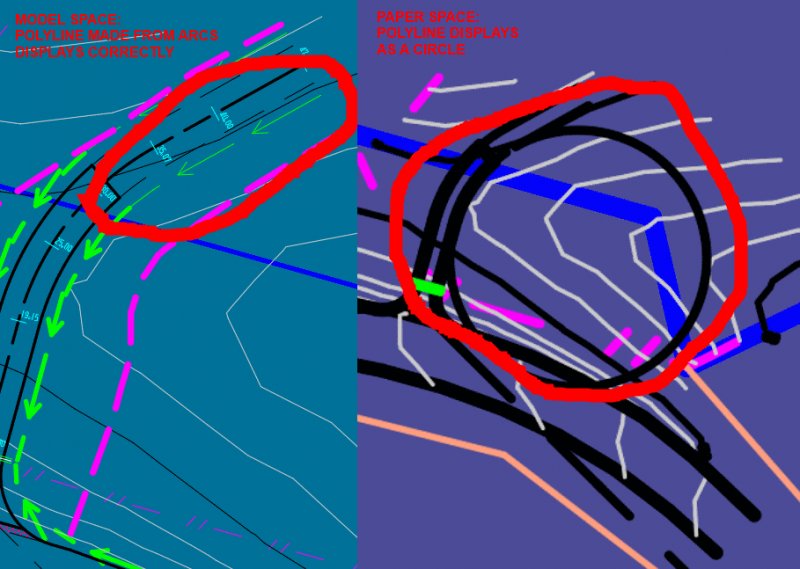
Hi all I'm working on some information that I have imported into LT 2017 from 12D survey software. Basically I have a road string (polyline made up of arcs) and I'm tidying it up. All I have done to this string is break it and change the layer it is on. When I go into Paper space and look at my plan layout, the broken polyline displays as though it is a full circle. In Model space it looks how it ought. I have double-clicked in the viewport and selected the circle and changed the colour for easy identification. Then, when I go back to Model space, I have a red curved polyline. No circle. I have also tried copying the polyline as a block and pasting it into paper space. It displays as it ought to. If I paste it back into Model Space, it retains its characteristics - i.e. curve in model space, circle in paper space. If I explode the polyline into its component arcs and join them together again, it begins to behave properly. This never used to happen in prior versions of CAD, and my co-worker has had a similar problem. She says it's not a consistent fault - sometimes the display behaves and sometimes it doesn't. I have run audits and purges and all sorts of fun things and have achieved nothing. It prints correctly, but the preview shows it as a circle also. Any ideas, or similar issues?
-
I am writing a LISP to find subtle kinks between curves. Right now I'm stuck on finding all the angles. Is there an efficient way to do this? I'm hoping to find the angles between connected curves, including arcs and polyline curves, and then highlight (draw a red circle?) around all angles with less than 20 degrees difference (160 to 200 degrees) between the lines. If possible I'd eventually like it to be able to automatically smooth the kinks, but I think that that part will have to come at a later time. On a completely unrelated note, I can't stop seeing this as a cyclops.
-
I'm making an Audi R8 as a project but how can I extrude an arc on an angle? I'm trying to extrude from the top view to make the body side arcs.
-
 I attached the plan I am having trouble with. It is named first_plan.dwg. I created some lines with the arc tool and joined them to represent the electrical wiring in the layer called electrical wiring. I changed the linetype to a dotted and dashed style but it won't display in the model space and layout 1. Nor will it display when I hit print preview. Can someone point out to me what I am doing wrong? I am new to AutoCAD and this is my first plan. I am using AutoCAD 2015 for Mac. first_plan.dwg
 -
Having trouble making dotted and dashed lines for electric lighting. Please help.
moredew780 posted a topic in AutoCAD Beginners' Area
I attached the plan I am having trouble with. It is named first_plan.dwg. I created some lines with the arc tool and joined them to represent the electrical wiring in the layer called electrical wiring. I changed the linetype to a dotted and dashed style but it won't display in the model space and layout 1. Nor will it display when I hit print preview. Can someone point out to me what I am doing wrong? I am new to AutoCAD and this is my first plan. I am using AutoCAD 2015 for Mac. first_plan.dwg -
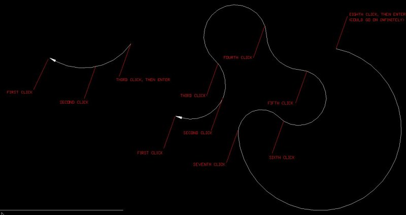
When I used to use R14, I had a customized leader command where the first click was the endpoint of a leader (as usual), the second click was like the midpoint of an arc, and the third click was the other endpoint of an arc. You could continuously keep clicking and producing more arcs connected to the leader block, but typically I would just end the leader there, and it would not end with a text attached to it. Since I upgraded to AutoCAD 2010, the LISP function that I used for that did not transfer over, but I would like to have that again, as the spline leaders that are standard in 2010 look terrible compared to what I used to have, and are nowhere near as versatile. Is there a place I can find a LSP command to do the same thing, or will I have to rewrite the new command again? Here are some examples of how the finished 'CLeader' looked:
-
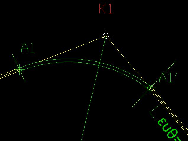
Hi all, I design concrete swimming pools... I have a drafting issue that hopefully someone can shed some light on. I have attached a diagram for your reference. I need to draw a curved line that starts tangent to segment (A) and hits points 1-3 and ends tangent to segment (B). The floor of a pool obviously is a smooth curve, not a segmented line. I would love to be able to represent that accurately. Any ideas?? Pool Section 2.dwg
-
Hey, I am tracing a curvy 2D shape using arc function. I want the outline of the shape very smooth. I would like to know how do I draw arcs that can be tangent to each other so eventually I can get this shape very smooth and nice. Thank you very much!
-

Arcs tangent to two other arcs/circles
andymccallum posted a topic in AutoCAD 2D Drafting, Object Properties & Interface
How do I draw an arc/circle tangent to two other arcs/circles? Ultimately, I am trying to create a snail cam drawing. -
I need a lisp routine that can take a long polyline and delete all the arc segments, thus leaving multiple shorter polylines (all consisting only of straight segments). Can anyone help me with this please?
-
This is the text-book exercise I am working on: Strictly speaking, the back of the jaw consists of two arcs and a tangent. I can't find anything in the book so far that deals with this so I am stuck. Can someone please help me out with a way to do the back of the jaw. Thanks BTW: as to the dimensions, I work in millimetres so I take the given imperial (inch) dimensions, multiply the number by 100, and call it mm. Hanger_Jaw.ipt
-

how to connect 2 arcs? what is the correct way?
Sengna posted a topic in AutoCAD 2D Drafting, Object Properties & Interface
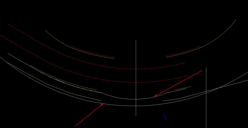
I tried to connect these arcs together as you can see on the red arrows but they didn't look smooth, i use 3 points arc and another mothod was circle command. How would you guys do it?
-
Hello guys, well i have a homework for the exams and i have no time, so i need your help. The question is, how i can measure the exact length of an arc (or a polyline) ? See the pic.
-

Create a polyline arc that mimics the shape of a building
RichardLloyd posted a topic in AutoCAD 2D Drafting, Object Properties & Interface
Hi there all, I am new here so forgive me if my question is vague or likewise is a bit over the top. I have been sent a client's construction drawing for a care home where i need to design the sprinkler installation. The majority of the rooms have got the same head positions within them, but they have all got a slightly different angle as the building is shaped like a banana. Unfortunately its not a uniform radius that i can tell as the one side is larger than the other. So my question is this. Normally, on a square building, I drop in construction lines along the bedrooms so that i know my sprinkler heads are all the same distance off a wall, and I only need to line up one side. However, with this building being a curve, and the wall angle being slightly different on each room, how do I place an angled construction line or polyline to act as my set out line for my heads. Ive been looking at the drawing and various forums now for the past 2-3 hours and still haven't seen an answer that helps greatly. Thanks in advance, Richard