

Creating Bryce Picture Objects
The image pairs found in the CADTutor Download area can be used to create Picture Objects in Bryce. This short tutorial tells you how this is done in 7 simple steps. The screen shots shown here are from Bryce 4.
Step 1
Download a pair of images from one of the CADTutor Image Bank pages. Right-click one image at a time, and choose "Save Target As…" from the context menu. See the Download Main Page for more details. Save the two images to a convenient folder on your computer.
Step 2
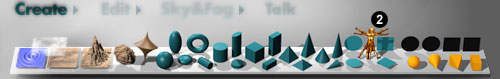
Start Bryce and check that the Create toolbar is displayed. If not, click on "Create" to display it. Now, look for the gold Leonardo-man on the toolbar. This is the Create Picture Object icon. Click the icon to move to the Picture Library.
Step 3
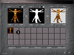
The Picture Library consists of two main areas, a row of 3 preview windows at the top and 30 thumbnail buttons below. By default, only the Leonardo-man is displayed. The 3 preview windows represent, from left to right, the colour channel, the so called "alpha channel" and the result of combining the two channels. What you are about to do is to load the colour image into the colour channel and the mask image into the alpha channel. The result will be a cut-out image. First, pick one of the blank thumbnail buttons. A file dialogue box will appear. Navigate to the folder where you saved your downloaded images and select the colour image. Click the "Open" button.
Step 4
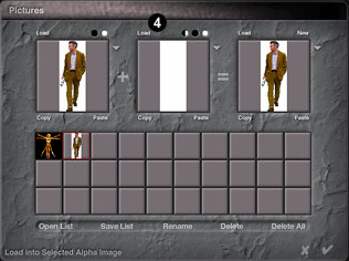
In step 3, you used the blank thumbnail button to load the colour image to the colour channel and you should now see this image displayed in the left-hand of the 3 preview windows at the top of the Picture Library. You should also see this image in the right-hand preview window showing the result of your channel combinations. A thumbnail of the image also appears on the button you picked. The next step is to load the mask image into the alpha channel. To do this, click on "Load", just at the top left of the middle preview window. Once again you will see a file dialogue box. This time, select the mask image and click "Open".
This whole process can be made easier if you have an image file that contains both colour and alpha channel information. If you load such a file in step 3, step 4 becomes unnecessary because both channels are loaded simultaneously. Such a file can be created in Photoshop using CADTutor Image Bank image pairs. See the Creating Selections from Image Masks tutorial to find out how this is done.
Step 5
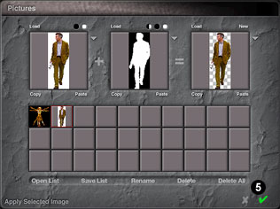
In steps 3 and 4, you loaded images into the colour and alpha channels to define a new image in the Picture Library. You should now see the results of your efforts. The left-hand preview window shows the colour image, the middle window shows the mask image and the right-hand window shows the combination of the two channels. Effectively, any black in the mask image is interpreted as being transparent and any white is interpreted as opaque. The resultant cut-out is displayed against a grey-and-white checker pattern. This is the usual way of expressing transparency in graphics programs. Notice that the thumbnail button does not show the combination image, only the color channel information. Click the ![]() button at the bottom right of the Picture Library to create your new picture object.
button at the bottom right of the Picture Library to create your new picture object.
Step 6

You are now returned to the wire-frame scene and you should see your new image object as a highlighted rectangle somewhere in the middle of the scene. You may find that your image object is not sitting exactly on the ground plane. In the example shown on the right, the man-01 image object has been placed with it's base below ground level (this image has been rendered to make it clear what's going on). However, rectifying this situation is very simple. Since the image object is currently selected (and if it isn't, pick it to select it), you will see a set of edit buttons displayed in a column beside it. The lowest of the buttons is the "Land Objects Up/Down" button and the arrow displays the direction in which the object will be moved in order to land it on the ground plane. Obviously an object can be either above or below the ground plane so the arrow will point down or up respectively. To have your picture object stand on the ground plane, simply pick this button and the picture object will be moved as required.
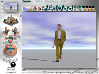
Step 7
Finally, to see your image object as a fully integrated part of your scene, you must render the scene. Click the large central render button at the bottom of the control panel. When the render is complete, your scene should look something like the one in the illustration below.
Donate to CADTutor
If you found this tutorial useful, you might like to consider making a donation. All content on this site is provided free of charge and we hope to keep it that way. However, running a site like CADTutor does cost money and you can help to improve the service and to guarantee its future by donating a small amount. We guess that you probably wouldn't miss $5.00 but it would make all the difference to us.
Local Navigation
Sponsored Links
The Basics
- Dual Dimensions in a Dim…
- UCSICON Options
- "Best of" Basics: Irreg…
- Tool Palette Basics
- Original Dimension Value
- Possible Solutions to th…
- Avoid Using 'Standard' i…
- Shorten the Plot Scales…
- Update the Source File B…
- User Increment Angles fo…
- Drawing Information
- 'Sign Language'
- Rotate with the Copy Opt…
- Use the INSERT Osnap on…
- To or From the Current L…


