Search the Community
Showing results for tags 'coordinates'.
-
I'm looking for a way to extract the X, Y and Z values from a set of selected blocks (there may be several types of blocks) and then have it export to a txt file. I'm not sure if it's possible but I'd like to have it export in the order that the blocks were placed. The format I'm looking for would be like this: x,y,z x,y,z and so on... I can do it in Microstation but would prefer an Autcad Lisp. Any help is really appreciated!!!!!
-
We often have ditches in roadway cross sections. I create a feature line to model the bottom of the ditch, so that there's a target for the slope into the ditch. My question is, is there any way to specify a point by providing a station and an offset off the road alignment, so that I can place the feature line nodes accurately? What I've been doing is 1) draw a series of circles centered on where the sample lines cross the centerline; 2) draw the feature line with each vertex at the intersection of a circle and a sample line; 3) provide the elevation based on the elevation needed in the cross section. Yes, it would be more efficient to draw one long segment and let AutoCAD extrapolate the elevations, but our ditches never line up that neatly. A better question might be, is there a more efficient way to create a ditch in cross sections? Up until now, we've been doing all this by hand. Judging by the lack of discussion on this particular item, it's so easy nobody has problems, or they're doing it manually too.
-
Hi mates, any idea to get the geo-coordinates of a Position Marker (new entity in Autocad 2016)? I tried to extract like a block attributes, but it doesn't work. Thanks in advance.
-
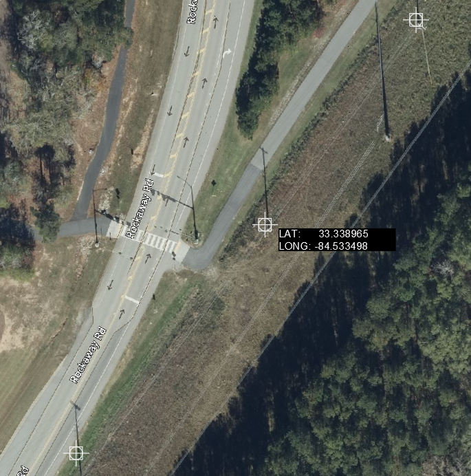
Hello everybody, Currently using Cad 2022 Map 3D, I have around three to four hundred GPS points for existing poles and probably more coming, I'm looking for a way to display their respective Lat and Long on the model space on Mtext format like the sample below, any help would be greatly appreciated. I know that your time is valuable. Thank you 116617090_GPSTest.dwg

-

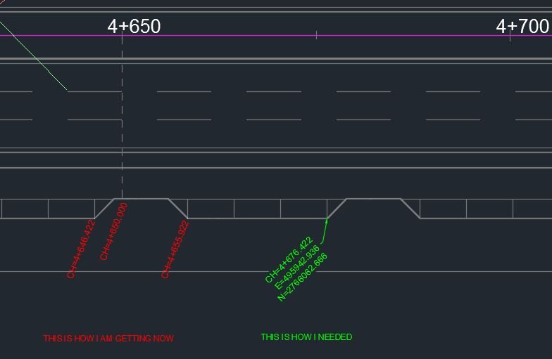
Change in lisp to get E,N Coordinates added to CH.
minejash posted a topic in AutoLISP, Visual LISP & DCL
hai, i need help.i have a working lisp routine which gives perpendicular line distance to main pline when clicked on a place perpendicular, all i want to add is the leader at the where i click and Easting and Northing and CH. and also instead of TEXT i need MText position where i can click. pls reply if its possible. i've added a screenshot for reference ..... thanks:) (defun c:Chi (/ s p c a d tp sch) (setq sch (getstring "\nSpecify start chainage : <0>")) ;"0" is set as the default value (if (= sch "")(setq sch "0")) (if (and (setq s (car (entsel "\nPick a polyline :"))) (or (= (cdr (assoc 0 (entget s))) "LWPOLYLINE") (alert "Invalid object! Please pick a polyline only.") ) ) (while (and (setq p (getpoint "\nSpecify point perpendicular to polyline :") ) (setq c (vlax-curve-getclosestpointto s p)) (setq a (angle p c)) (not (grdraw p c 1 -1)) ;; rubber line in red colour. (setq d (angle '(0. 0. 0.) (vlax-curve-getfirstderiv s (vlax-curve-getparamatpoint s c) ) ) ) (or (or (equal (rem (+ d (* pi 0.5)) (+ pi pi)) a 1e-4) (equal (rem (+ d (* pi 1.5)) (+ pi pi)) a 1e-4) ) (alert "Picked point is not a perpendicular to picked polyline. <!>" ) ) (setq tp (getpoint "\nSpecify Point for Text : ")) ) (entmakex (list '(0 . "text") '(100 . "AcDbEntity") '(67 . 0) '(370 . 13) '(100 . "AcDbText") (cons 10 tp) (cons 40 0.6) ; Change text height here (cons 1 (strcat "CH=" sch "+" (rtos (vlax-curve-getdistatpoint s c) 2 3) ;3 instead of 4 to specify precision ) ) (cons 71 0) (cons 72 0) (cons 11 '(0 0 0)) '(100 . "AcDbText") (cons 73 0) ) ) ) ) (princ) ) (vl-load-com)
-

Get Z coordenate from a point or 3Dpolyline
toxicsquall posted a topic in AutoLISP, Visual LISP & DCL
I'm having a problem getting a Z coordinate from a point or a object, like a 3dPolyline. I need to put a text in front of it. I have this one, but it only gets the X and Y coordinates and I just need the Z coordinate. -
Hi Everyone, I am having a problem using the command in geological location command. is it possible to set the actual location of my project in google map using this command? I don't have access to plex earth. Please help me to enlighten. Thank you,
-
Hello, I am looking for the next lisp. I need to create a plline (for example a rectangle) wherever I want inside the model. Then, the routine will ask me about the distance between coordinate tic marks (x) , the plot scale (1/500 for example) and the height text. Then I will click the rectangle and finally it will create all the coordinate tick marks inside the rectangle as an editable objects (block for example) with its coordinates N (vertical) and E (horizontal). I am attaching a dwg Thanks, Best regards, Daniel. 1.dwg
-

coordinates extraction per polyline, together with hyperlink text
mariarfd posted a topic in AutoLISP, Visual LISP & DCL
Hello, I recently discovered the potential in acad with lisps, and first of all I want to thank all the people sharing their knowledge (specific thanks to Tharwat and GC gile)! I am completely ignorant regarding what seems like programming here, but I am very willing to try and learn (allready succeeded in changing a parameter in a lisp all by myself!) The facts are: I have lots of closed 2d polylines (or lwpolylines, doesn't really matter because I have learned how to turn my polys into lwpolys). I have to extract their area, layer and coordinates, in a way that each polyline's data can be identified in the resulting file. I started by researching a way to automatically name the polylines, not much luck, so I am determined to enter numbers manually in the hyperlink field for each polyline. I have also found a lisp that extracts hyperlink, layer and area for multiple polys at once, which is a great first step (as a newbie I am not sure if I can post the link here). What now remains is to extract each poly’s coordinates together with its hyperlink. Do you think it is doable to invent a routine and achieve this for many polylines at once? Alternatively I will have to list and copy paste the coords for each polyline separately... for 400 polylines ... and then again in another similar dwg... etc. Sorry for the large thread, I hope I explained properly – and sorry if the answer already exists somewhere, I did my best to find it but didn’t (I did find quite some lisps to export coords, without separation per polyline and without hyperlink. Maybe someone experienced could alter these to include the extra data, but this is not my case…) Many thanks in advance to all the helpfull inlightened people here, Maria -

get coordinates from model space to paperspace vb.NET
Wiktuors posted a topic in .NET, ObjectARX & VBA
hello, i am pretty new at vb.net and i am stucked at converting coordinates from model space to paper space, so please help at this. Actually i need some examples how to get coordinates from model space point to paper space (for example i am selecting point in model space and other point in paper space and i need to draw a line between them(visually) in paperspace. Or maybe i can add object to array in modelspace(that i could have right coordinates), do CHSPACE and get these objects in paperspace array(that i could have new objects' coordinates)? Sorry for my english, if someone can help pm or reply.. -
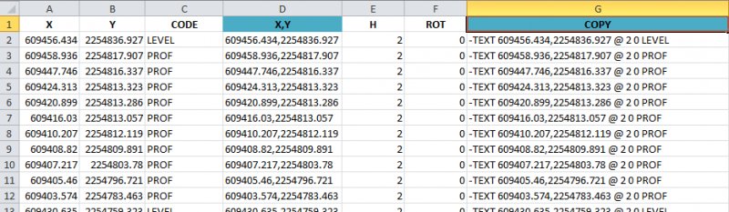
Sample.dwg Hi all, I want to write a program which will export the coordinates of vertices for selected polylines with Object Data which corresponds to each polyline. Please refer to a sample drawing attached with this thread. I am happy with this program to export coordinates ; ---------------------------------------------------------------------- ; (Export LWPOLYLINE Vertices & Points to File) ; Copyright (C) 2000 DotSoft, All Rights Reserved ; Website: http://www.dotsoft.com ; ---------------------------------------------------------------------- ; DISCLAIMER: DotSoft Disclaims any and all liability for any damages ; arising out of the use or operation, or inability to use the software. ; FURTHERMORE, User agrees to hold DotSoft harmless from such claims. ; DotSoft makes no warranty, either expressed or implied, as to the ; fitness of this product for a particular purpose. All materials are ; to be considered ‘as-is’, and use of this software should be ; considered as AT YOUR OWN RISK. ; ---------------------------------------------------------------------- ;;Revised 8/23/07 CAB to report coordinates in current UCS (defun c:ptexport () (setq sset (ssget '((-4 . "<OR")(0 . "POINT") (0 . "LWPOLYLINE")(-4 . "OR>")))) (if sset (progn (setq itm 0 num (sslength sset)) (setq fn (getfiled "Point Export File" "" "txt" 1)) (if (/= fn nil) (progn (setq fh (open fn "w")) (while (< itm num) (setq hnd (ssname sset itm)) (setq ent (entget hnd)) (setq obj (cdr (assoc 0 ent))) (cond ((= obj "POINT") (setq pnt (cdr (assoc 10 ent))) (setq pnt (trans pnt 0 1));;**CAB (princ (strcat (rtos (car pnt) 2 "," (rtos (cadr pnt) 2 "," (rtos (caddr pnt) 2 ) fh) (princ "\n" fh) ) ((= obj "LWPOLYLINE") (if (= (cdr (assoc 38 ent)) nil) (setq elv 0.0) (setq elv (cdr (assoc 38 ent))) ) (foreach rec ent (if (= (car rec) 10) (progn (setq pnt (cdr rec)) (setq pnt (trans pnt 0 1));;**CAB (princ (strcat (rtos (car pnt) 2 "," (rtos (cadr pnt) 2 "," (rtos elv 2 ) fh) (princ "\n" fh) ) ) ) ) (t nil) ) (setq itm (1+ itm)) ) (close fh) ) ) ) ) (princ) ) (princ "\nPoint Export loaded, type PTEXPORT to run.") (princ) Now I want to add Object data such as: 1. For polylines on 'LVCable' layer - CSAMetric, Conductor, FeederNo, NoOfCores 2. For polylines on other layers - CSABlue, CSANeutral, CSARed, CSAYellow, FeederNo Thank you Best wishes, Jes G Sample.dwg
-
I usually do extensive research before posting a question to this forum, but I have not been able to find the answer I'm looking for. I'm trying to create a lisp that asks you for a plane (getkword "X Y or Z <Y>:") Then pick a point (getpoint "\nSelect Point) Pick blocks (setq blks (ssget '((0 . "INSERT")))) Finally aligns all blocks to the selected plane. I have a Lisp that does this, except that when the blocks have attributes, the attributes stay in place and I would have to manually move them. I know that a way to do it is to select all blocks i want and go to the properties and change either the X Y or Z values, but that also seems tedious. Any help is greatly appreciated. Thanks.
-

accessing entity in a codes windows selection set
maerfl posted a topic in AutoLISP, Visual LISP & DCL
Hello I'm not able to figure out how to easily access the first entity of a slection set created with coded windows selection. I want to read out coodinates of the first point of 2 different objects which are "grabed" in a coded windows selection set. One polyline, one line. Then I want to copy the line from it's first point as basepoint to the first point of the polyline. Advanced I would like to copy it to all the other points of the polyline too. So it would be further more interesting to know how to access (read out the coordinates of) the second, the third and so on point of an object...using visual lisp. The following code is using first a pick up of the object where the line should be copied to and a static coordinate for the basepoint of the line instead of a read out coodinate: (vl-load-com) (setq sel1 (ssget "_w" '(-2 -2) '(115 10))) (setq e (car (entsel))) (setq topoint (vlax-curve-getStartPoint e)) (command "_.COPY" sel1 "" "0,0" topoint) -
Hello guys, I'm trying to make a lisp to import points from txt file to autocad, and then to polyline them and to make a union from those points, creating a iregular area. The main purpose is to calculate the area of this created object. The txt file is something like this: 101 234.442 442.425 102 ..... 103.... 104... 105... Anyone there that could help me with this lips ? I kinda need it until tomorow.
-

Count Specific Block Name and Insert Block to Coords Depending on Block Count
kylaughlan posted a topic in AutoLISP, Visual LISP & DCL
Hi there, I'm looking for a Lisp routine that can count the number of one specific nested block (it will always have the same name) within a single layout, and then automatically insert the same block (which doesn't need to be nested) to differing coordinates depending on how many of that block there already is. I am having doubts to whether this would even be possible but I thought I would ask. Seeing as nested blocks can be counted through Lisp, I figured it might be possible. I've began to explore the world of Lisp and am using a few different routines currently. They work great but I am nowhere near at a stage where I can write a detailed Lisp routine myself. [using AutoCAD 2017 full version] Thanks guys, Kyle -
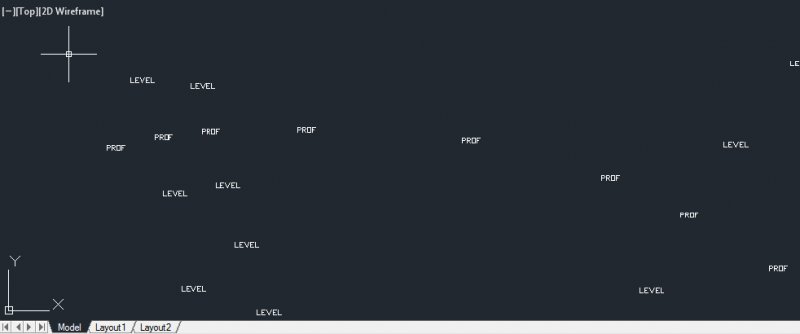
Hi, i'm want to import the code (or description) from csv file (X,Y,Code) on the coordinates of each point. I can do it in excel, but i'm looking for a easy way. The layer could be current, height 2, and rotation 0. I can change this properties later, so no problem about it. Please excuse my limited English, corrections are welcome. Many thanks in advance.
-

Trouble with xyz coordinate import LISP
philnesterovic posted a topic in AutoCAD 2D Drafting, Object Properties & Interface
Hi all, I am using the attached lisp to import xyz (PNEZD) coordinates into Autocad 2015 with their points numbers and descriptions. The lisp works great, the only problem is that when all the points are put in, I can't change the colour and layer of the attached descriptions and elevations. The points themselves will change colour and layer, but we can't get the writing to move to those same layers. I'm not sure if this requires working on the lisp itself, or if it is something that can be fixed in a setting in Autocad, but I'm definitely stuck! Any help would be greatly appreciated. Thanks! pointsin-v1.0.13.zip -

Draw a Lot using Latitude and Longitude from Google Earth
Subiran posted a topic in AutoCAD Beginners' Area
Hi. I'm a beginner in CAD, I'm going to ask how to draft a lot using the coordinates(latitude and longitude) from google earth. Example: Point A. Latitude: 11 Degree 18'2.22"N Longitude: 124 Degree 57'46.89"E Please check my attachment picture. -

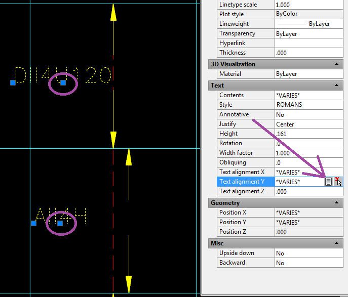
Help Aligning Various Pieces and Setting Coordinates
EatingSteak posted a topic in AutoCAD 2D Drafting, Object Properties & Interface
Hello all, I'm trying to align some text blocks and arrows, but I'm having a clumsy time navigating AutoCAD's "features" related to doing this. Quick demo pasted below I have my text centered, and want to align them to my (red) centerline. But whenever I select two blocks and try to Move them, the "grab handles" go away. If I have a lot of items to move, it's tedious to do one at a time. On the corner, there is a QuickCalc button where I can pick the exact coordinate I want, but when I try that, it sets ALL coordinates at the same time, where I only want to change the Y. If I try to calculate an absolute Y-coordinate, then it won't move if I resize the column, so I'd rather not do it that way. Is there a way I can highlight a bunch of items and just hit a button to "Center all Y-coordinates at [Click here]"?
-

Extracting the coordinates from a rectangle in modelspace
chiimayred posted a topic in AutoLISP, Visual LISP & DCL
Hey guys, I'm trying to get the four corners of a rectangle in modelspace set to variables and I'm having a hard time with it. I'm able to get the four corners into a list, but I'm having a hard time setting each coordinate to a variable. The issue I'm having at this point is that the second variable duplicates the coordinate values. The first variable Here's what I got so far... (defun c:test (/ ptlist x y) (setq ptlist (massoc 10 (entget(car(entsel))))) (defun c:massoc (key alist / x nlist) (foreach x alist (if (eq key (car x)) (setq nlist (cons (cdr x) nlist)) ) ) (reverse nlist) ) ;end (princ ptlist) (setq x (car ptlist)) (setq y (cadr ptlist)) (princ) (princ x) (Princ) (princ y) ) I got part of this code from here When I draw in a rectangle in modelspace and I use this code, this is what I'm getting. Command: TEST Select object: ((18.2488 -11.0958) (23.6419 -11.0958) (23.6419 -5.32136) (18.2488 -5.32136))(18.2488 -11.0958)(23.6419 -11.0958)(23.6419 -11.0958) So it builds the list and sets the first variable right, but it duplicates the second. Thanks in advance! e: I haven't added in error trapping yet, just trying to figure this out first. -
hi, I have a little problem with a lisp file that extract coordinates from DWG and label them with prefix and counters then export them to text file. if anybody can advice how to exit this lisp correctly i would really appreciate it a lot. (defun run () (setq pll (getstring "\nPlease Enter of new file (name.ext) :")) (setq pl (open pll "w")) (setq ang ( getreal "\nPlease Enter DV Angle: " ) ) (setq n ( getstring "\nPlease Enter TAXI name: " ) ) (initget (+ 1 2 4)) (setq a ( getint "\nPlease Enter MH number: " ) ) ;(setq e (getstring "\nget no. of first Point :")) ;(setq a (atoi e)) (while (> a 0) (setq aa 1) (while (<= aa 4) (setq p (getpoint "\nselect point :")) (setq v1 (strcat "\n " (itoa a) " " (itoa aa) " ")) (setq d (polar p (dtr 90) 0)) (setq f (itoa aa)) (setq k (itoa a)) (setq g (strcat n "-" k "-P-" f)) (command "layer" "m" "number" "c" "3" "" "") (command "text" "m" d 0.2 ang g) (setq num (entlast)) ;(command "change" num "" "layer" "" number "") (command "change" num "" "p" "layer" "number" "") (command "layer" "m" "point" "c" "1" "" "") (command "point" p) (setq pt (entlast)) ;(command "change" pt "" layer "" point "") (command "change" pt "" "p" "layer" "point" "") (setq x (car p)) (setq x (rtos x 2 4)) (setq x (strcat x " ")) (setq v2 x) (setq y (cadr p)) (setq y (rtos y 2 4)) (setq y (strcat y " ")) (setq v3 y) (princ V1 pl) (princ v2 pl) (princ v3 pl) (setq aa (+ aa 1)) ) (setq a (+ a 1)) ) (command "layer" "m" "txt" "c" "5" "" "") (close pl) (redraw) (princ) ) (defun c:I () (run) (setq fil (getstring "\nget name of the file (name.ext) :")) (setq p1 (getpoint "select insertion point :")) (setq p2 (polar p1 0.0 35.0)) (setq p3 (polar p1 0.0 105.0)) (setq p4 (polar p1 (/ (* -1 pi) 2) 20.0)) (setq p5 (polar p4 0.0 35.0)) (setq p6 (polar p4 0.0 70.0)) (setq p7 (polar p4 0.0 105.0)) (setq p8 (polar p2 (/ (* -1 pi) 2) 10.0)) (setq p9 (polar p8 0.0 35.0)) (setq p10 (polar p8 0.0 70.0)) (setq p11 (polar p8 (* -1 pi) 15.0)) (setq p12 (polar p8 (/ pi 2) 5.0)) (setq p13 (polar p8 (/ (* -1 pi) 2) 5.0)) (setq p14 (polar p12 0.0 35.0)) (setq p15 (polar p13 0.0 17.5)) (setq p16 (polar p13 0.0 52.5)) (setq p1- (polar p1 (/ (* -1 pi) 2) 2000000000.0)) (command "text" "m" p11 3.0 0.0 "POINT NO.") (command "text" "m" p14 3.0 0.0 "COORDINATES") (command "text" "m" p15 3.0 0.0 "X") (command "text" "m" p16 3.0 0.0 "Y") (command "line" p1 p4 "") (setq L14 (entlast)) (command "line" p2 p8 p5 "") (setq L285 (entlast)) (command "line" p9 p6 "") (setq L96 (entlast)) (command "line" p3 p10 p7 "") (setq L3107 (entlast)) (command "line" p1 p2 p3 "") (command "line" p8 p9 p10 "") (command "pline" p4 p5 p6 p7 "") (setq L4567 (entlast)) (setq fill (open fil "r")) (read-line fill) (setq new ()) (setq j 0.0) (setq p44 p4) (while (setq S (read-line fill)) (setq pt (polar p44 (/ (* -1 pi) 2) (+ 5 j))) (setq pt1 (polar pt 0.0 12.5)) (setq pt2 (polar pt 0.0 50)) (setq pt3 (polar pt 0.0 85)) (setq t1 (substr S 1 4)) (setq t11 (strcat n t1)) (setq t2 (substr S 5 18)) (setq t3 (substr S 23 32)) (command "text" "m" pt1 3.0 0.0 t11) (command "text" "m" pt2 3.0 0.0 t2) (command "text" "m" pt3 3.0 0.0 t3) (setq p4 (polar p4 (/ (* -1 pi) 2) 10.0)) (setq p5 (polar p5 (/ (* -1 pi) 2) 10.0)) (setq p6 (polar p6 (/ (* -1 pi) 2) 10.0)) (setq p7 (polar p7 (/ (* -1 pi) 2) 10.0)) (command "offset" (+ j 10.0) (list L4567 p4) p1- "") (setq new (entlast)) (command "extend" new "" (list L14 P4) "") (command "extend" new "" (list L285 p5) "") (command "extend" new "" (list L96 p6) "") (command "extend" new "" (list L3107 p7) "") (setq j (+ j 10.0)) ) ;(close) (close fill) ) (defun dtr (x) ;define degrees to radians function (* pi ( / x 180.0)) ;divide the angle by 180 then ;multiply the result by the constant PI ) (princ)
-
I have set in autocad the correct angle settings, have been applying 20 different functions to obtain the correct angle (Y axis) between two coordinates, but I keep getting strange angles back from this routine. Either the correct angle is difference with 90, or 450. Any idea why? I have gone through most of math forums on the internet. I need the angle correctly in order to scale a polygon. thanks. Public Function GiveAngle(DegRad As Boolean, x1 As Double, y1 As Double, x2 As Double, y2 As Double) As Double Dim Xdist, Ydist As Double Dim ATAN3 As Double Dim PI As Double PI = 3.14159265358979 Xdist = (x2 - x1) Ydist = (y2 - y1) If Abs(Ydist) > Abs(Xdist) Then If Ydist > 0 Then ATAN3 = Math.Atn((x2 - x1) / (y1 - y2)) Else ATAN3 = Math.Atn((x2 - x1) / (y1 - y2)) + PI End If Else If Xdist > 0 Then ATAN3 = 0.5 * PI - Atn((x2 - x1) / (y1 - y2)) Else ATAN3 = -0.5 * PI - Atn((x2 - x1) / (y1 - y2)) End If End If GiveAngle = ATAN3 * 180 / PI End Function
-
How do you turn off the coordinates(12.1588,1.7770,0.0000) that show up from the previous value(5) entered on command line so the value of last entered(5) shows up when using the keyboard up arrow? This done using the 'move' command.
-
Hi Guys, Is it possible to use Pscom object to get shapes coordinate? World or UCS both OK. I have a set of UCS points like this by using list command in prosteel. Med Res PolyCount=1 Med Nr=0 X=-152.500000 Y=-154.000000 Bulge=0.000000 Med Nr=1 X=152.500000 Y=-154.000000 Bulge=0.000000 Med Nr=2 X=152.500000 Y=-146.300000 Bulge=0.414214 Med Nr=3 X=144.800000 Y=-138.600000 Bulge=0.000000 ...... Need to output them to other applicaiton. It is a W310 beam. KS_Shape and KS_ShapeInfo didn't work. Please help.
-
I have a AutoCAD plan with roughly 1000 points . I want to display a sl. number along side the respective points and then generate A excel file with point number and their co ordinates. I am very new to AutoCAD. Can anyone give me detailed procedure how to do this?? Thanks in advance