Search the Community
Showing results for tags 'display manager'.
Found 2 results
-
Posted this at the Swamp too, hopefully something comes up. I'm having a bit of an issue trying to dig through the Display Manager to get the proper visual outcome for my Plan View mechanical piping. I simply started a QNEW drawing template defaulted from ACAD MEP. Using the MEP Design Display Configuration, any pipe that is 10" and larger shows up double line. When pipe is crossing over other pipe, it shows the hidden lines like you would expect, gives proper visual look of flanges, valves, etcetera. But in this Display Configuration any pipe 8" and smaller it shows single line, it has a symbolic "X" for flanges, etcetera. The only way to get everything to have a proper visual look of any size pipe, MvPart, or connection fitting is to change the Display Configuration to MEP Basic 2-line. In doing this, I lose the hidden line feature, so it looks very wireframe and can get messy in certain drawing situations. I have been digging and trying countless combinations in the Display Manager and I cannot figure out for the life of me what setting I need to adjust so that I can get (1) all sizes to show double line, (2) all MvParts and connection fittings to show properly, and (3) still have the hidden line feature functioning properly to provide accurate plan view visual information for the drawing. Any ideas? Thanks in advance. :wink: PS: Using AutoCAD MEP 2011.
-

Plot problem - a COPY of raster seems to jump to front during plot, then disappears?!
Tallguy posted a topic in Map 3D
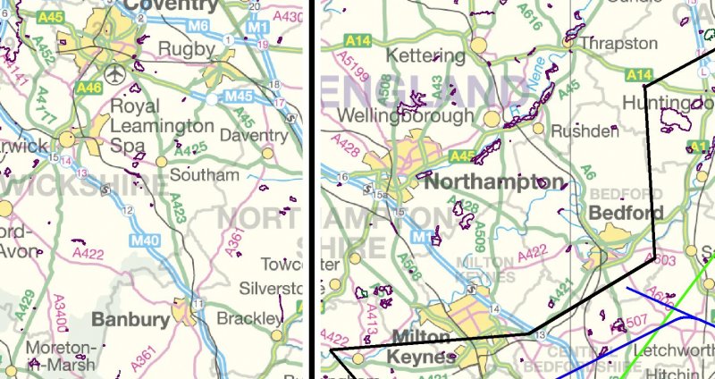
Hi CADTutors, this is an odd one. I'm plotting polylines, SHP data and a background raster. Until yesterday, all was well. Today, odd things are a-happenin'. This is a screenshot of the sort of thing I want to plot: The purple areas are CONNECTED and STYLED (in Display Manager) shp data, the black/white/blue/green lines are polylines, the raster background (GB Ordnance Survey Miniscale tile) is STYLED in Display Manager as Raster>>>33pc fade. When I plot to jpg, I get the same selected area of print, but just the OS tile UNfaded and nothing else. When I plot to PDF, and i open the PDF, I can watch the PDF "build" itself and the correct data is there (as per the screenshot) BUT it then gets "covered up" by the OS tile, unfaded. From this, I surmise that it's plotting everything correctly BUT then putting a copy of the UNfaded Raster tile ON TOP of everything, obscuring it. . I only know this 'cos the PDF build-up shows me what it's doing. It didn't do this until yesterday, and this has happened before but "it just sort of came back". I tried the following today, no luck: All the various "send to back" options for the raster >> wouldn't explain the un-fading. WBLOCK out the polyline data, create a new DWG, INSERT block, re-import the raster and re-connect and STYLE the SHP file. Restart my machine and do all of the above. Restart my machine and not run any other applications (Outlook, Internet Explorer etc). Hit the monitor with a binder until it bleeds liquid crystal, and otherwise act like a child having a tantrum . That was satisfying but ultimately unproductiveo:). What's most annoying, apart from all the annoying stuff, is I can see it's gonna happen. During the plot process (I love watching a little progress bar fill up from left to right), I see my display turn white, then this un-faded raster fills the screen, plot completes, the un-faded raster disappears and leaves my screen as per the screenshot. I check the plot and hey presto! it's screwed. In effect, I think it's laughing at me. Dear, dear AutoCADists, please could you help? Or, failing that, could you just send me money to soothe me? Pounds Sterling is fine, as is U$D or €Euros...