Search the Community
Showing results for tags 'piping'.
Found 8 results
-
Version 1.0.0
4,818 downloads
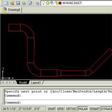
This is a program made by ASMI and modified by Ronso in this thread. This is a genius free LISP Program and can be used in many trades, but has most usefulness in the HVAC, Mechanical, and Piping industries for drawing 2D CAD designs. It allows you to create Duct, Pipe, and Segmented Duct or Piping with automatic elbow or fittings to accurate dimensions via some initial input at the command prompt. The programme in action Function Syntax: DUCT For instructions on how to run the program see here. -
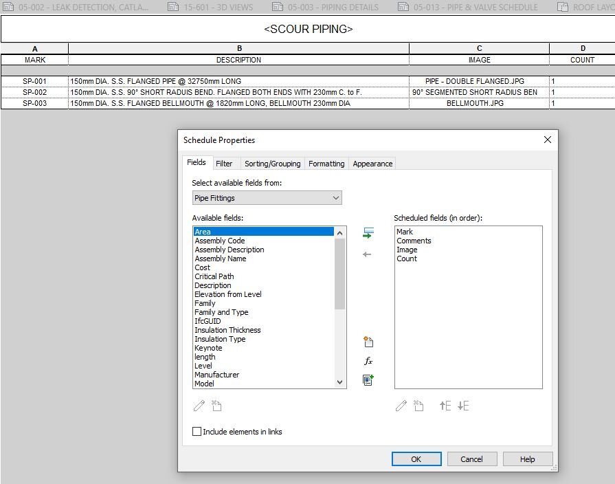
Good Morning. I have been working on setting up a pipe schedule for my current project. Prior to Revit i was using AutoCAD for piping and scheduling which was very tedious. However the pipe schedule format is prefered by our suppliers/contractors and clients and we want to keep the format. i have attached a image for reference (Labeled Example). The AutoCAD schedule was done manually. I have created a relatively automated Revit Schedule, but it needs more refinement and i do not know how to proceed. i have added screen shots to show the schedule i have created. I have used a Tag family to tag the pipe fittings according to my sequence. (This is fine) The comments (description) i have to manually type. (I would like this Automated including the length of the pipe/angle of the elbow/distance the puddle flange is from the flange etc taken from the fitting) The image is a screen shot which is added as a image (this is not ideal , i would like an image that can be dimensioned as in the AutoCAD schedule or as in a window or door legend.) The count is calculated by the number of pipes that have the same tag (This is fine) so this is my goal, and i feel that it should be doable, i just do not know how to go about making it happen. any advice, tips tricks or guidance would be really appreciated

-
Posted this at the Swamp too, hopefully something comes up. I'm having a bit of an issue trying to dig through the Display Manager to get the proper visual outcome for my Plan View mechanical piping. I simply started a QNEW drawing template defaulted from ACAD MEP. Using the MEP Design Display Configuration, any pipe that is 10" and larger shows up double line. When pipe is crossing over other pipe, it shows the hidden lines like you would expect, gives proper visual look of flanges, valves, etcetera. But in this Display Configuration any pipe 8" and smaller it shows single line, it has a symbolic "X" for flanges, etcetera. The only way to get everything to have a proper visual look of any size pipe, MvPart, or connection fitting is to change the Display Configuration to MEP Basic 2-line. In doing this, I lose the hidden line feature, so it looks very wireframe and can get messy in certain drawing situations. I have been digging and trying countless combinations in the Display Manager and I cannot figure out for the life of me what setting I need to adjust so that I can get (1) all sizes to show double line, (2) all MvParts and connection fittings to show properly, and (3) still have the hidden line feature functioning properly to provide accurate plan view visual information for the drawing. Any ideas? Thanks in advance. :wink: PS: Using AutoCAD MEP 2011.
-

Automatic dimensions and bills of material for piping components
mechaniker posted a topic in AutoCAD Beginners' Area
Hi Is there a way to choose a piping class based on ASME B16.5, then a component and its size, and let AutoCad automatically show their dimensions in the isometric drawing and create a bill of materials? Thanks a lot -

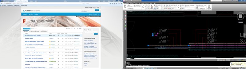
Cannot edit objects in fabrication,only stretch Using CADMEP2013, Fabrication loaded
RMcHugh123 posted a topic in MEP
Hello Can someone please help with the attached drawing. I cannot edit the pipework only stretch etc. maybe i dont have the right catalogs or settings?
-
I've been learning this program and believe it's the best program to use for modeling future underground utilities on the project I'm on. I've been able to create new pipe sizes and materials and have been able to set inverts and rim elevations, but I realized that it's not modeling the diameter of the pipes correctly. I'm in the proper units and my lengths dimesion properly, but say if I select a 48" HDPE pipe to be drawn, when it's modeled I can measure the diameter and it says 4.25". So, it's converting almost every 12" to 1". A 4" iron pipe models as 3/8" diameter. I've played with multiple new files and units, but can't seem to get it to model at the true diameter. Even if I scale the drawing it does not scale the diameter, only length. Is there something simple I'm missing? Thanks for any help.
-
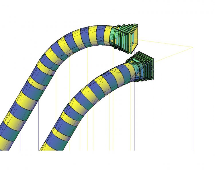
I am new in 3d, and i would like to know how to draw this pipe as shown in this picture below. Kindly teach me to draw a 3d pipe with horizontal curve and vertical curve elements combined. Here are the design elements : for the horizontal curve for the vertical curve radius=30.798m radius=18.000m angle=29deg angle=60deg The diameter of pipe that i am trying to draw is 5 meters. Thanks in advance.
-
Hello, I'm currently taking a Basic AutoCad class at school. I just got assigned a group project where everyone draws an assigned 2D wblock and when the class is finished we're going to piece the wblocks together to make one large drawing. I know how to make the wblock but my problem is I don't understand these dimensions or how to use them to make my drawing in AutoCad and was hoping I could get some help here. I am assigned to draw a 4" Tee pipe (2D) and I have a sheet of poorly scanned paper with a table giving me the Nominal Pipe Size, Outside Diameter, Center to End of Run, Center to End of (I think it says Branch? it's very poorly scanned so it has a smudge over the letter next to the "B" so it looks like B?anch). I really have no idea on how to go about this and it is due tomorrow night at the end of class. Under the Nominal Pipe Size category the dimensions that pertain to 4 are: Outside Diameter: 4.500 Center to End of Run: 4 1/8 Center to End of B?anch: 4 1/8 If I recall correctly our teacher told us to round off the numbers to 4 which doesn't make any sense at all to me. Any help at all is appreciated.