Search the Community
Showing results for tags 'plot'.
-
Hi, I looking for some guidance on creating a script that will allow me to plot selected layouts to a specified folder location. I have tried the below, but it will only plot to the same location as where the drawing is stored. I can't seem to find where I enter the folder location below. I have attached my script, I can't use a Lisp command as I am only using an LT version of the software. plot Y DWG to PDF.pc3 ISO full bleed A3 (297.00 x 420.00 MM) Landscape No Layout FIT Ortho ON -Osnap app,ext,mid,int,cen,qua,tan,per,end,par,ins,node,nea, Viewres Y 20000 Zoom e Regenall 2.F_(Rev_C01).scr
-
Hello to everyone! I wand to create a lisp file that prints on a loop while hiding and unhiding different layers. I am working on a cad software called 4MCAD. 4MCAD unfortunately does not have the native Autocad DWGtoPDF printer. The main problem I am facing is that I have to use third party printers to plot to PDF which ask for the name of the PDF file name on a seperate window. I have tried Nitro PDF creator, cutePDF, doPDF and I cannot figure out how to supress the pop-up window while giving the desired name to the PDF file. Has anyone know how to solve this problem? Can you get DWGtoPDF printer as system printer so my Cad software can find it? Has anyone suceeded with any third party software at giving the file name inside the lisp file? For example let's say that the desired filename is "C:\DWG_prints\DWGpr1.pdf" and I want a command like this: (command "-plot" "n" "" "" "" "n" "n" "" "C:\DWG_prints\DWGpr1.pdf" )
-
Hi Guys I came across the following routine, from https://forums.autodesk.com/t5/forums/forumtopicprintpage/board-id/130/message-id/336228/print-single-message/false/page/2 However, when I tried it it gives me an error message ; error: no function definition: LM:ODBX How can I get this to work and also change the default size to A1 rather than A2. (defun c:RV ( / ) (LM:ODBX (function (lambda ( doc ) (princ (strcat "\nOpening file : "(vla-get-name doc))) (vlax-for lay (vla-get-layouts doc) ; (if ( = "Model" (vla-get-name lay)) ; (progn (setq PaperSize "ISO_A2_(594.00_x_420.00_MM)");-----default paper size (princ "\nSearching for Title Block") (vlax-for blk (vla-get-blocks doc) (cond (( = (vla-get-name blk) "Title_A4") (setq PaperSize "ISO_A4_(297.00_x_210.00_MM)")) (( = (vla-get-name blk) "A3 Drawing Sheet") (setq PaperSize "ISO_A3_(420.00_x_297.00_MM)")) (( = (vla-get-name blk) "Title_A2") (setq PaperSize "ISO_A2_(594.00_x_420.00_MM)")) (( = (vla-get-name blk) "Title_A1") (setq PaperSize "ISO_A1_(841.00_x_594.00_MM)")) );cond );vlax-for blocks (princ (strcat "\nPaper Size Assigned : " PaperSize)) ; );progn ; );if model space (vla-put-ConfigName lay "DWG To PDF.pc3") ;set the plotter (vla-put-CanonicalMediaName lay PaperSize) ;set the paper size---> (vla-put-PlotType lay "1") ;plot area extens (vla-put-CenterPlot lay "1") ;center plot (vla-put-PaperUnits lay "1") ;set units to mm (vla-put-PlotWithLineweights lay "0") ;turn off lineweights (vla-put-PlotWithPlotStyles lay "1") ;turn on plot styles (vla-put-StandardScale lay "0") ;fit to paper (vla-put-stylesheet lay "Grayscale.ctb") ;set the CTB (princ (strcat "\nPlot settings done for : "(vla-get-name lay))) );vlax-for (princ "\n--------------------------------------------------") ) ) nil t ) (princ) );defun
-
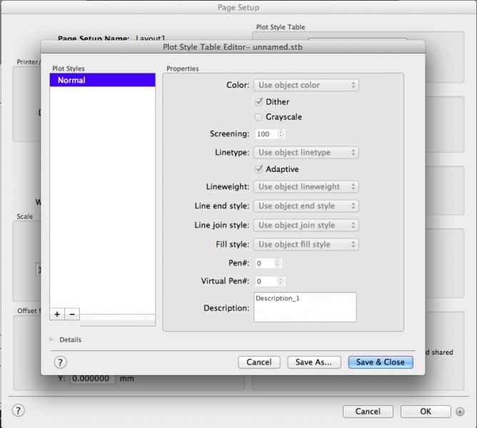
 Hi, I've just started using AutoCAD and would need to print out my first piece of work. I'd like to create a new plot styles so that my layer colors don't print as displayed (i.e. I want my blue, red and white layers to print as black and my green layer to print as yellow). According to all tutorials/instructions I should get a long list of colors (color 1, color 2, color 3 etc) under "plot styles" in the plot styles table editor. However, there are no colors there. Just one that says "normal". How can I choose which layer color to print as what color if I have nothing to choose from? I have attached a screen shot of my plot style table editor. Please could anyone help? I'm using a student version of AutoCAD 2015 (version J.51.M.256) Thanks, Sofia
-
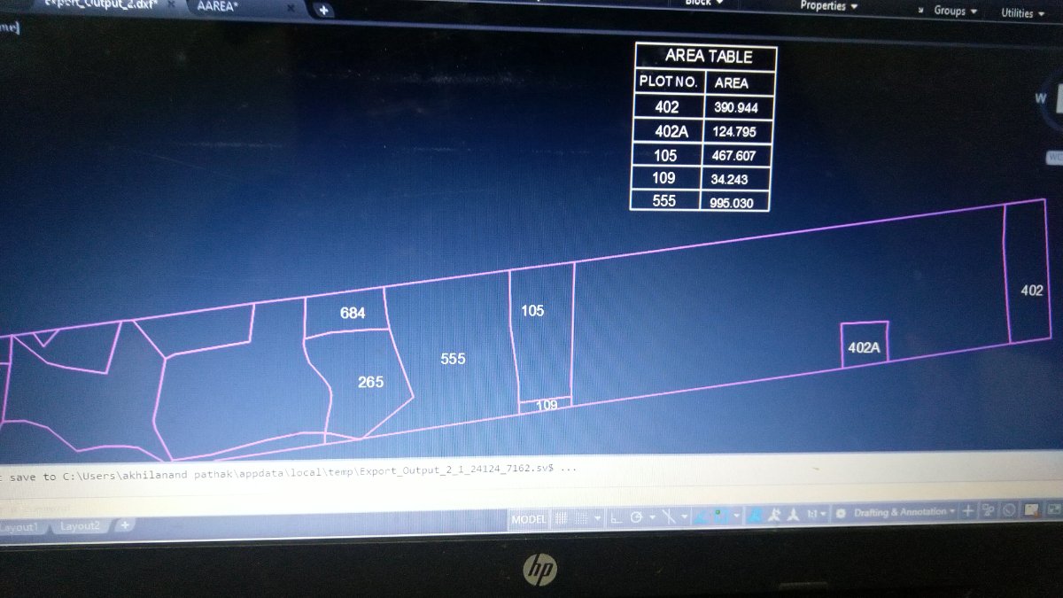
Dear members, Any lisp program or trick to make a area table From a plan. I want a area table with plot number text along with area . I will select all at time, the automatically generate area table. Please See the attached image. AREA TABLE OF POLYGON.dwg
-

Select specific named layouts and save them in a folder as a PDF
Manuel_Kunde posted a topic in AutoLISP, Visual LISP & DCL
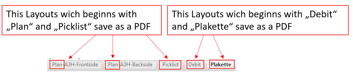
Hi Guys, I have several layouts when drawing, which also have different names. I want to save in a Lisp all layouts that start with a specific name in a certain folder as PDF. I am new in lisp, but i have managed to write a lisp that selects the correct location for me. Unfortunately only all layouts are printed. (defun c:Dokument_Export () (command "-EXPORT" "PDF" "ALLE" (strcat (substr (getvar "DWGPREFIX") 1 70) "\\08_Auftragsbestätigung\\" (strcat (substr (getvar "DWGNAME") 1 8) "_Zeichnung") ) ) ) You have any idea? Thanks in advance.
-
Hello, I am new in AutoCAD. I draw 1:1 floor plan, I draw 1m in real like 1 in autocad. Now I have to plot it in pdf as 1:50. How can I do that
-

All workstations the same DWG to PDF plot settings
Pietari posted a topic in AutoCAD Drawing Management & Output
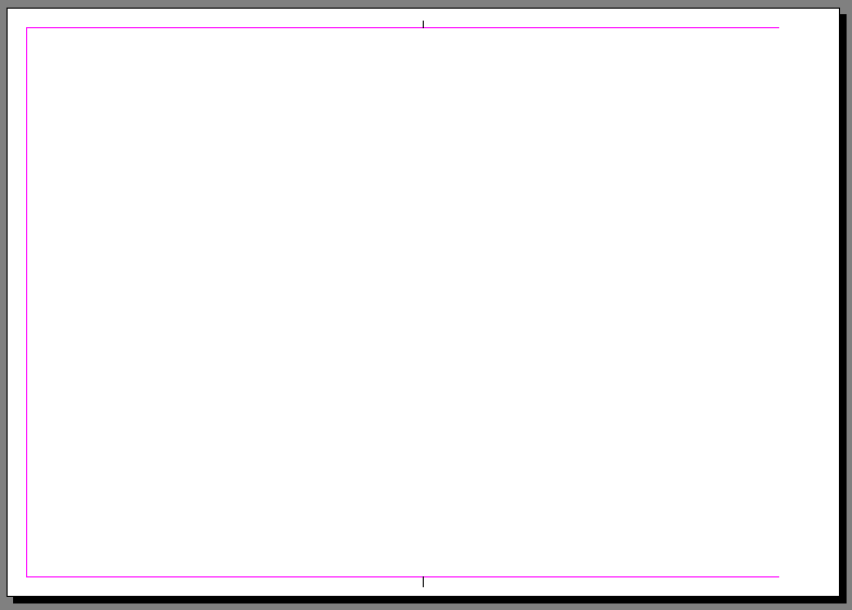
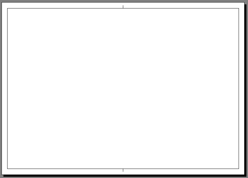
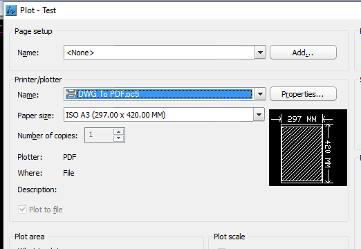
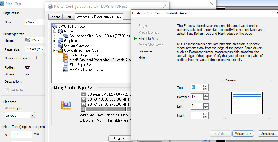
Hi guys, This one has been giving me some headache. Could anyone of you point me into the right direction, I'd be most thankful. Software used: ZWCAD2014 on a Windows 10 machines. For those who may not know about ZWCAD: it is an actual and legal clone of AutoCAD 2012 official purchased at dealer store, the software is created by ZWSOFT. Just think of it as AutoCAD 2012, it makes understanding easier :-). In our company we have 8 workstation using the same ZWCAD program We only plot / publish from the layout tabs We all use DWG to PDF as it came with the software The created PDF's are send by email or they get plotted on our printer/plotter for internal use So far so good... but the problem is when I create an A3 (for example but it is the same on any paper size) it plots normal to a good looking PDF. If the same DWG is opened by one of my collegues, the plot gets cropped off, there are parts missing. I have attached the example output. I know fore sure some of us (me including) have tried to change the plottable area ages ago, reason for that was that the "default DWG to PDF" had way to big of a non printable area. To be in short: my DWG plots good on my workstation, and my collegues DWG plot okay on his workstation. But between all of the workstation it all gets messed up. We cannot plot each others drawings to PDF without having problems with the plottable area. I thought, let me check all the settings in the driver (see attachement) and I have put them all the same on another workstation. It did not change at all. At last I tried copying my PC5 file to the collegues.... still nothing changes. Now I can only think of a complete "re-install" of the software in order to get them working the same all the same once again. Before uninstalling and reinstalling the ZWCAD program and it's utilities, I'd thought maybe I'd ask here if someone could help me out. Thanks for the help!
-
Hi all, my lisp knowledge is very limited so I was hoping someone could help mw with this. I have a lisp which I copied from a Autodesk forum (https://forums.autodesk.com/t5/visual-lisp-autolisp-and-general/export-to-pdf-lisp-routine/td-p/5704455) and tweaked a little to suit my needs. It basically plot all layout tabs to PDF (with revision letter at the end of the pdf name). It works just fine. Now, what I want it to do is to instead of printing all layouts, read a csv file "title_block.csv" and only plot to PDF layouts named in that csv file (column B) starting from cell B2. It would be similar to what Lee Mac's UpdateTitleBlockV1-9 does to update title blocks. Any help would be much appreciated Cheers #(vl-load-com) (defun c:demo (/ hms:get_atts filename hnd lst lst1 name otab path ss) (defun hms:get_atts (enm / att obj) (if (or (and (eq (type enm) 'ENAME) (setq obj (vlax-ename->vla-object enm)) (eq (vla-get-hasattributes obj) :vlax-true) ) (and (eq (type enm) 'VLA-OBJECT) (setq obj enm) (eq (vla-get-hasattributes obj) :vlax-true) ) ) (mapcar '(lambda (att) (cons (vla-get-TagString att) (vla-get-TextString att)) ) (vlax-invoke obj "GetAttributes") ) ) ) ;;(cond ((setq path (acet-ui-pickdir "Select directory" (getvar "dwgprefix"))) ; check that pdf directory exists (cond ((setq dwgpre (strcat (getvar "dwgprefix") "PDF")) (if (= (vl-file-directory-p dwgpre) nil) (vl-mkdir dwgpre) ) (setq pdfname (strcat (vl-filename-base (getvar "dwgname")))) ;----------------------------------------------------------------------- (setq otab (getvar 'CTAB)) (foreach layt (layoutlist) (setvar 'CTAB layt) (if (setq ss (ssget "_X" (list '(0 . "INSERT") '(2 . "A1 TITLE NCL - new logo") '(66 . 1) (cons 410 (getvar 'CTAB))))) (progn (setq hnd (ssname ss 0) lst (hms:get_atts hnd) ;lst1 '("DRAWING_NUMBER" "SHEET_NUMBER" "REVISION_NUMBER" "SHEET_SIZE") lst1 '("RV") name "" ) (foreach n lst1 (if (setq a (assoc n lst)) (setq name (strcat name "-" (cdr a))) ) ) (setq sht (strcat(getvar "ctab"))) (setq filename (strcat dwgpre "\\" pdfname "-" sht " Rev " (vl-string-left-trim "-" name) ".pdf")) ;(command "_.-export" "_PDF" "_C" "_YES" "ISO full bleed A3 (420.00 x 297.00 MM)" "_M" "_L" "1:2" "_YES" "A3.ctb" "_YES" filename) (command "_.-PLOT" "Y" ;Detailed plot configuration? [yes/no] Layt ;Enter Layout name or [?],layout1: "Dwg To PDF.pc3" ;Enter an output device name "ISO full bleed A3 (420.00 x 297.00 MM)" ;Enter paper size "M" ;Paper units: "M" for mm "L" ;Enter drawing orientation: "L" for Landscaping "N" ;Upside down? "N" "E" ;"E" for extents "1:2" ;Plot scale: Custom "1:2" "C" ;Counter "c" "Y" ;Plot Style? "y" "A3.ctb" ;Enter plot style: "A3.ctb" "Y" ;Plot line weights? "N" ;plot line scaling? "N" ;Paper space first? "N" ;Hide? filename ;Directory to save "N" ;save changes to page setup? "Y" ;proceed with plot? ); command ) ) ) (setvar 'CTAB otab) ) ) (princ) )#
-

LISP FOR PDF CONVERT MULTI DRAWING IN MODEL BY USING PAGESETUP
SANTHOSH_PSK posted a topic in AutoLISP, Visual LISP & DCL
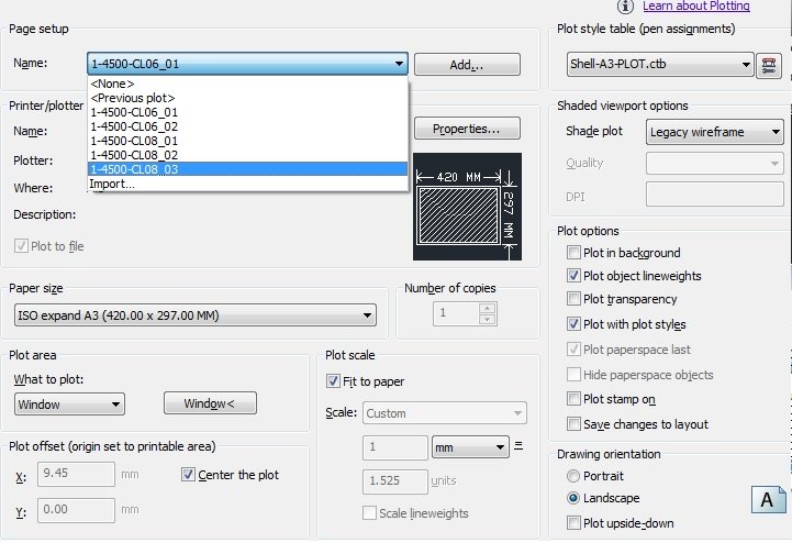
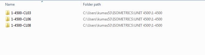
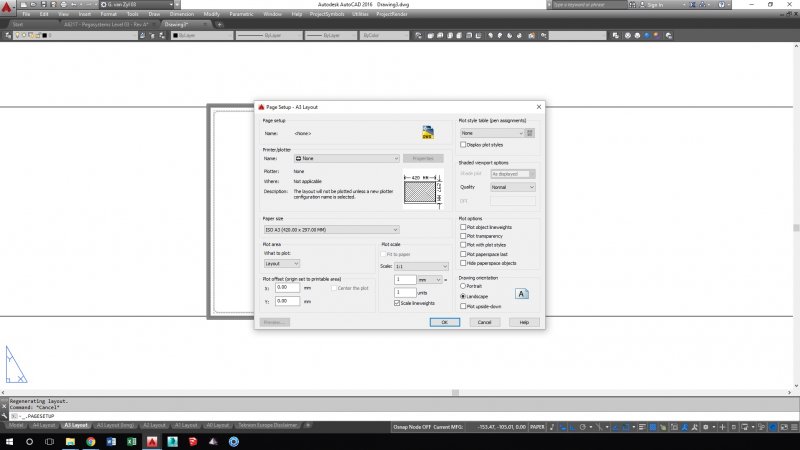
Dear Team, Greetings..! I have multiple drawings in one .dwg file in Model (Ref. UNIT 4500.JPG file). I need to covert PDF's with help of "Page Setup Name" Each name Plot area selected. (Ref. Page Setup.jpg file). the converted pdf file with name of same as Page setup name & automatically saved in WRT to Unit path.(Ref. Path.JPG) Kindly help me out I have hundreds of drawing to covert every time of small correction..!!
-
This code used to work fine for plotting to a .pdf: (defun c:SendToPDFefa() (vl-load-com) (if (setq filename (getfiled "Save File Location" "" "pdf" 1)) (progn (command "-plot" "yes" "" "DWG To PDF.pc3" "ANSI expand B (11.00 x 17.00 Inches)" "inches" "landscape" "yes" "Extents" "fit" "center" "yes" "acad.ctb" "yes" "a" filename "no" "yes") ) ) ) Now it fails with this output: Command: SENDTOPDFEFA Unknown command "P:\randomfolderstructure\ACADFILENAME.PDF". Press F1 for help. Unknown command "NO". Press F1 for help. Unknown command "YES". Press F1 for help. nil I know IT had been adjusting printers when this happened, but i don't know if that is coincidental. I have two questions: How does the code need to be adjusted What could have caused the code to fail Greg
-

Lineweight not plotting to thickness
GISdude posted a topic in AutoCAD 2D Drafting, Object Properties & Interface
Hi all, I'm at my wits' end on this. I have a few drawings that WON'T plot a LINE according to the LINEWIDTH that I've specified in the LAYER PROPERTIES MANAGER. Usually it's just changing the MSLTSCALE to 1 (or vice versa). But these handful of drawings aren't working. I do plot by PLOT STYLE, but still nada. I have searched high and low on various forums, but no go. I have a feeling there must be a variable I'm missing (I just upgraded to 2018MAP 3D). Thx all, -
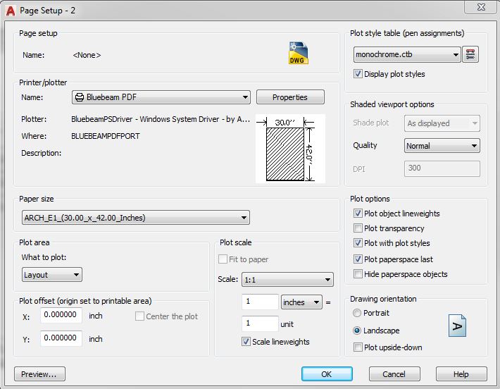
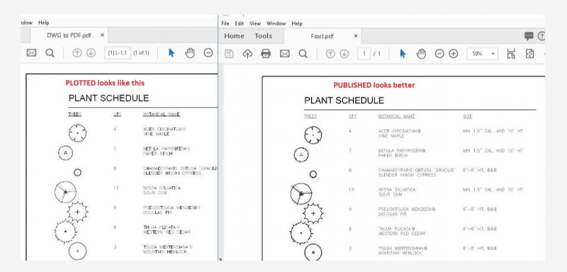
Hello, I have moved to a new office with a new computer, and I am trying to set up ACAD to where it PUBLISHes all the sheets to a single PDF, with PUBLISH quality (not plot quality). I have ten (10) layouts in a drawing, and all the layouts are set up the same way in Page Setup mgr. In page setup manager, for each one of the layouts, I've selected the BlueBeam PDF printer/plotter, an ARCH_E1 _(30.00_x_42.00_Inches) Paper size, a 'Plot style table' set to monochrome.ctb (SHOULD IT BE .stb???) with 'display plot styles' checked. Actually, just see this: Here are the problems: 1. The computer wants to publish by plotting ONE SHEET AT A TIME AND ASKING ME WHAT TO NAME IT AND WHERE TO PUT IT EACH TIME.. 2. The quality of the resultant PDF is terrible, and looks like it was plotted individually instead of published (I have noticed a difference between plotting and publishing). See this: I need some assistance, please! Thanks!
-
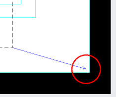
I have an odd issue with AutoCAD 2014. I have two different files which should be identical when I go to plot- exact same xref'ed title block, same paper size set, same plot style, same output (dwg to pdf in this case). This particular title block is set to plot properly at 1:1 paperspace on Arch D 24x36 by window, with center the plot selected. Sure, I could fit to paper, but then everything would be a tiny bit out of scale. I've triple-checked all of these settings between the two files; I even changed drawing units to mm temporarily and measured both title blocks in paper space to make sure they were the exact same size. However, in one file the title block doesn't fit - both sides hang off the paper space by a tiny bit. I can't think of what variable I'm overlooking that may be causing this. The outputs should be exactly the same, but one file refuses to play nice and fit the whole title block to the plot area! EDIT: I think I know what the problem is, but not how to fix it. See attached image. Basically, I need to get the intersection of the dashed lines to the center of the red circle (follow the blue arrow). That's how the correct file looks when it plots.
-

Publish is plotting drawing in lower right side rather than full page
juicyorange posted a topic in AutoCAD Drawing Management & Output
Hey guys, I am having an issue I've never seen before. I am trying to publish a set of drawings into one PDF file with DWG to PDF. However, when I do it looks like this (blackout added): When I zoom extents the drawing, it shows there's nothing out there. The page size is 11X17 and it plots to that size. When I plot the drawings individually it looks like this: I am really stumped on what it could be and welcome any insights. -
Hi i got a plot plan to redraw in autocad, but something looks off with the bearings. I know bearing usually looks like this S30D57'08"E but the bearings on the plan looks like this N19d36'47" there is not direction at the end of it.
-
plotting in modelspace - cuts off part of drawing (only in some drawings)
GISdude posted a topic in AutoCAD Drawing Management & Output
HI all, I'm trying to plot in model space and the printer is cutting off part of the drawing. I choose plot-->extents --> center the plot --> fit to paper. The x coord is always 0, however the y coord is always at .09280. I've tried adjusting the y to 0, and unchecking the plot, but the cutoff always happens. Keep in mind, this is in a handful of drawings. I've plotted to a different plotter (XEROX) and it works perfectly fine. I've switched the PLOTOFFSET variable and it makes the problem worse. My fear is this is a driver issue, Canon doesn't support this plotter anymore. Many thanks for any help. autocad map3d 2012, win7. -

Help needed - MText sometimes not showing up in plot
connorhagan posted a topic in AutoCAD Drawing Management & Output
We are getting some serious issues with plotting in Autocad. In one of our drawings, someone dimensioned the diameter of a circle. Here is where things get weird: It showed up in Paper space. It showed up when it was plotted to our Ricoh printer. When it was plotted to our HP Designjet the MText was gone. No dimension line, no text, nothing. The weirder thing is this behavior is inconsistent. I've plotted it on two separate computers and it shows up just fine. But sometimes it won't show up at all. Has any one else experienced this issue or a similar issue? Or does anyone know any reason that MText will sometimes not show up when plotted to a certain printer? -

how to print multiple files in one sheet?
khoshravan posted a topic in AutoCAD Drawing Management & Output
I have four simple drawings in 4 separate files. I want to print them in 4 corners of one A4 sheet. What is the easiest way to accomplish this task? -
Hey everyone, I am new to this whole forum thing, so I apologize if I should be starting a new thread but I do have a question related to this that I was hoping you could help with. I have been trying to automate my plotting process using MColor 9 which is a extension to CAD for color renderings. The issue is I am trying to plot multiple tabs at once, or back to back automatically. The command for plotting with Mcolor is "MCO_PLOT", but it will only do one tab at a time. I have created a LISP that has gotten me really close to where I want to be, which is: (defun C:mco-plot () (foreach lay (layoutlist) (setvar 'ctab lay) (command "_mco_plot") ); end foreach ); end defun *I changed the new command from "mco_plot" to "mco-plot" so it did not conflict. This LISP will automatically plot each tab back to back, but the hang up is that on each tab it asks me where I want to save the PDF. What I really need is something to add to this LISP function that will either have the PDF automatically save to the current drawings folder, or just have me specify the location once and save the PDF's for all the tabs in that location. I know this is unique because not everyone has MColor 9, I hadn't even heard of it before until my current job. However, I think there must be a solution out there since the only part I need now is a way to specify the saving location one time (one time per project) and then I would be good to go. Thank you for your time!
-
Hi All, So I am having an issue that I have never come across before and hoping to get some suggestions here to fix the issue. Basically my usual paperspace template with my titleblock now has really thick lines and the text has become invisible unless you hover over it. Just to clear up a few things: - I have checked my page setup and there is no difference to before and it is set up to match the correct page size. "Plot with plot styles" / "Plot object lineweights" are both turned off. - Lineweights are also turned off. - All layers are switched on and none have been frozen in paperspace / viewport. - No items are on "defpoints" layer. Also just to add that this is now happening to every drawing I am opening which makes me think that it is not related to one specific drawing, as it seems to be an autocad configuration issue. Any help would be hugely appreciated as I have some deadlines to meet and cant be plotting that as my paperspace view! Help please!
-
All, I need some help with this PDF plot lisp that was created at work, this lisp was created to take material list sheets PDF them and drop them into the source folder with the sheet name as the file name. I was wondering if someone could help figure out how to combine the pages together to create one file once they are converted to PDF all as one step. ;;;This is the lisp routine to Plot the material list to individual PDF files with the job name and the page number ;;;as is does in the Plot Material List button. ;;; plotpdf.lsp (defun c:PlotPDF (/ ob ss bn mn mx) (vl-load-com) (setq cnt 0) (setq dir(getvar "dwgprefix")) (if (and (progn (initget "B") (setq ob (entsel "\nSelect Block/B for blockname: ")) (cond ((eq ob "B") (setq bn (getstring "\nEtner Block Name: ")) ) ((and (eq (type ob) 'LIST) (vlax-method-applicable-p (vlax-ename->vla-object (car ob)) 'getboundingbox)) (setq bn (cdr (assoc 2 (entget (car ob)))))))) (tblsearch "BLOCK" bn) bn (setq ss (ssget "_X" (list '(0 . "INSERT")'(410 . "Model")(cons 2 bn)))) ) (progn (vla-zoomextents (vlax-get-acad-object)) (repeat (setq i (sslength ss)) (setq ML "Material-List") (setq cnt (1+ cnt)) (vla-getboundingbox (vlax-ename->vla-object (ssname ss (setq i (1- i)))) 'mn'mx) (command "plot" "yes" "model" "DWG To PDF.pc3" "ANSI A (8.50 x 11.00 Inches)" "inches" "LANDSCAPE" "no" "Window" (trans (vlax-safearray->list mn) 0 1) (trans (vlax-safearray->list mx) 0 1) "fit" "center" "yes" "acad.ctb" "yes" "As Displayed" (strcat dir "ML-" (itoa cnt) "-"(getvar "dwgname")) "no" "yes" "yes" "yes") (command ".delay" "750") ) ) (princ "\nNo Blocks Selected: ") )(princ) ) Thanks, Brian
-
Hi all! I'm new to AutoCad, having only done a few small jobs over the last year. Mainly floor plans for planning permission. I've finished the plan and I'm tearing my hair out trying to get it to export to PDF to scale. I've done a few before on A4 and they've been fine. I got the plan to 1:200 scale fine on A4 (weirdly, only when I set the scale to 1:20), but when I went up to A3, the scale was way off. A quick measure gave me a scale of around 1:143. I assumed printing at "actual size" from adobe onto A3 would simply give me a scale of 1:100. This is obviously not the case. This is an urgent job (needed to be completed yesterday!) and I've run out of ideas! Any help would be greatly appreciated.
-
Good afternoon. Well recently I saw a 3D PDF and I want to know if Autocad 2016 can plot a 3d object to this 3D PDF. Ist that possible? What and how I'll do such thing?
-

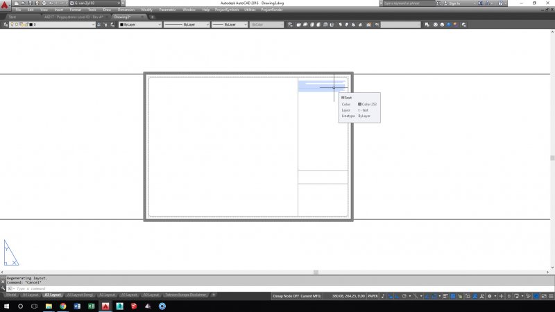
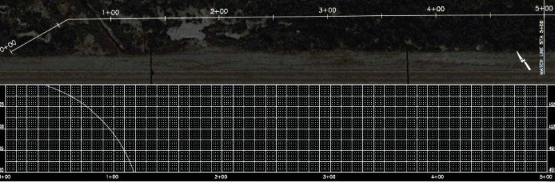
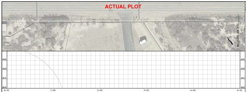
Raster Image looks out of place but isn't
hcostanzo posted a topic in AutoCAD Drawing Management & Output
Hello! I'm hoping someone knows a fix for this. I'm working on a large project, and I have 14000 feet of plan & profiles split into 500 ft sections, with a raster image as the background of all the plan views. The plan viewports are rotated 36 degrees using mvsetup. The problem is that when I go to any of the layout tabs to view my sheet the raster image appears to have shifted over, but when I plot the sheet the raster is in the correct spot and everything looks good. I would like to work within the layouts, but can't when the images appears out of place. Sorry for the long explanation, I just wanted to cover as much of the problem as I could. Any help is greatly appreciated, and thank you in advance!