

All About Images
See also, Using Images & Scaling Images
Introduction
AutoCAD is essentially a vector drawing application. However, there are occasions when it would be useful to display raster images as part of your drawing. It would also be useful if you could make basic modifications to images and to be able to scale them. Using such tools, you could use an image to trace some base information. For example, a raster map could be used to draw vector contour lines. You could also use raster images in place of vector symbols to add realism or personality to a drawing. Fortunately, such tools do exist within AutoCAD and although they don't approach the functionality of a dedicated raster image application such as Adobe Photoshop, they are adequate for most purposes.
This tutorial shows you how to use all of the tools on the Image section of the Reference toolbar, shown below. The tutorial will show you how to attach an image to an AutoCAD drawing and how to manipulate the image appearance. The tutorial also covers some of the extended image options included with Express Tools and how to control image objects with the Properties Window. If you would like to follow this tutorial closely, right-click the Tree Image on the right and download it to your work folder. When you have completed this tutorial, you may like to complete the Using Images exercise in order to get some practical experience. There is also a techniques tutorial, Scaling Images that demonstrates the best way to scale raster base information.
 |
To display the Reference toolbar in AutoCAD, select View![]() Toolbars… from the pull-down menu, scroll down the "Toolbars" list and put a check in the box against "Reference".
Toolbars… from the pull-down menu, scroll down the "Toolbars" list and put a check in the box against "Reference".
You can follow the tutorial from start to finish in order to learn all about images and AutoCAD. However, if you just need information quickly, use the QuickFind toolbar, above to go straight to the command you want or select a topic from the contents list.
Images & AutoCAD
The important thing to remember about images and the thing that causes most confusion amongst novice users is that they are not actually inserted into a drawing as the "Insert" pull-down menu might suggest. Image files are attached to AutoCAD drawings. In other words, images do not become an integral part of a drawing. AutoCAD merely looks for images that have been attached and loads them as required. There are pros and cons to this method.
Pros
- AutoCAD drawing files remain relatively small.
- Changes to images will be displayed each time a drawing is opened.
- It is consistent with the Xref (External Reference) method.
Cons
- If AutoCAD cannot find the image file, the image cannot be displayed.
- More than one file is required to display the drawing correctly.
When you attach an image to an AutoCAD drawing, AutoCAD remembers where the image file is located, this is known as the path. Each time the drawing is opened, AutoCAD uses the path to find the image file and displays it. This works fine providing both the drawing file and the image file remain in the same place. However, if like me, you travel around and work on different computers, this can cause problems. My solution is very simple and consists of just two rules:
- Always keep AutoCAD drawings and their attached image files in the same folder.
- Always deselect the "Retain Path" option in the Image dialogue box.
If you follow these two rules, it doesn't matter where your work folder is, on your home PC, on your work PC, on a USB drive or on a CD, AutoCAD will always find the image file when the drawing is opened.
Attaching an Image
| Toolbar | |||
| Pull-down | Insert |
||
| Keyboard | IMAGEATTACH | short-cut | IAT |
Attaching an image to an AutoCAD drawing is a relatively simple 3-step process. This involves selecting the image file, setting a few parameters and then picking points to position and scale the image.
Before inserting an image, it is a good idea to create a new layer for your image. This way, you can easily control the display of the image by turning the layer off or on. Use the Layers command ![]() to create a new layer called "Tree Image" and set it to be current.
to create a new layer called "Tree Image" and set it to be current.
To begin, start the Attach Image command from either the Insert pull-down menu or the Reference toolbar. The Select Image File dialogue box appears. Use the dialogue box to locate the image you want to insert or the Tree Image if you have downloaded it.
 |
|
 |
 |
When the file is selected, an image preview appears. To complete the selection, click on the "Open" button. The Image dialogue box displays and allows you to set various parameters that determine how the image will be attached. The Image dialogue box is shown below.

As you can see from the illustration above, the Image dialogue box has two main functions. Firstly it allows you to decide whether AutoCAD remembers the image path. See the Images & AutoCAD section above for a discussion on paths. Secondly it allows you to decide whether the position (insert point), scale and rotation of the image are specified on-screen or within the dialogue box. For most purposes, deselect the "Retain Path" checkbox. Other settings can be left to their default state. Your dialogue box should now look like the one shown above. Click the "OK" button to proceed.
Now look at the command prompt. AutoCAD will now ask you to specify the insertion point (the lower left-hand corner of the image) and the scale because these two parameters were set to "Specify on-screen" in the Image dialogue box. Follow the command sequence below to complete the command.
Specify insertion point <0,0>: (pick a point)Pick a point in the drawing area to fix the lower-left hand corner of the image. You needn't be too precise at this stage because you can always move the image later. However, you could always enter a co-ordinate value if you know exactly where the image should be placed.
Base image size: Width: 1.000000, Height: 0.967742, Unitless
Specify scale factor <1>: (scale dynamically)
To scale the image dynamically, simply move the mouse. You will see the image outline change size as the mouse moves. Pick a point when you are happy with the image size and the full image is displayed at the required size. If you want, you could enter a scale factor instead of scaling dynamically. The default scale factor is one. This means that the image will be inserted so that its width is one drawing unit. So, if you want the image to be five drawing units wide, you could set the scale factor to five.
The Image Manager
| Toolbar | |||
| Pull-down | Insert |
right-click | Image |
| Keyboard | IMAGE | short-cut | IM |
As the name suggests, the image manager is a general purpose utility for managing your raster images. Using the Image Manager, you can attach new images, detach existing images, unload and reload images, modify the image path and display image details such as pixel size, colour depth etc. The Image Manager is shown below.
The "Attach…" button enables you to attach images to the current drawing. It works in exactly the same way as the Image Attach command described above.
Sometimes you may want to remove an image from your drawing. You can, of course, simply erase an image but since you can have more than one instance of an image in your drawing, only that one instance would be erased and AutoCAD would still look for the image file when the drawing was opened. The only way to remove all instances of a particular image and to stop AutoCAD searching for the image is to detach it. To detach an image, highlight the image name in the list and click the "Detach" button. Beware of using the Detach button. Once an image has been detached, all position, scaling and clipping information will be lost.
If you just want to remove an image temporarily, it is far better to unload it. Unloading an image, removes the image from the drawing but AutoCAD remembers any position scaling and clipping information. When the image is reloaded, it will reappear just as it was before you unloaded it. To unload an image, highlight the image name and click on the "Unload" button. To reload an unloaded image, highlight the image name and click on the "Reload" button. When an image is unloaded, its boundary remains visible in the drawing. You can turn image frames off using the Image Frame command.
There are a number of reasons why you may want to unload an image. Firstly, images can take up quite a lot of computer memory and so your computer may work more quickly with images unloaded. Secondly, you may simply want to hide images so that the drawing looks clearer while you are working. Of course, you could also do this using layers if your images are on their own layer. See the Controlling Layer States section of the Object Properties tutorial for more information.
The "Details…" button displays a dialogue box showing all relevant information about a particular image. Notice that on the example below, the "Saved path" and the "Active path" details are different. This is because the "Retain Path" option was deselected when the image was attached. The saved path is where AutoCAD looks for the image file when the drawing is opened. In this case, it only looks in the folder where the drawing is saved. The active path is the actual location of the file on this computer. If I copied my working folder onto a Zip disk or to a different computer, the saved path would remain the same but the active path would change to reflect the actual location of the file. Click "OK" to clear the Image File Details dialogue box.
The "Image found at" area of the Image Manager allows you to change the active and saved paths of any attached image. You can change the image path either by clicking on the "Browse…" button and navigating your way to the image location or you can change the image path in the edit box. Changes made to the image path in this way will affect only the active path. If you want the changes to apply also to the saved path, you must click on the "Save Path" button.
Clipping an Image
| Toolbar | |||
| Pull-down | Modify |
right-click | Image |
| Keyboard | IMAGECLIP | short-cut | ICL |
The Image Clip command enables you to clip or hide part of an image. There are two types of clipping, Rectangular and Polygonal. A rectangular clip allows you to hide that part of an image outside of a defined rectangle. A polygonal clip allows you to hide that part of an image outside of a defined polygon. See the images below to see the effect of the two clipping types. Only one clip is allowed per image. However, you can apply different clips to different instances of an image.
 |
 |
 |
| Original Image | Rectangular Clip | Polygonal Clip |
To clip the Tree Image, start the Image Clip command and follow the command sequence below.
Command Sequence
Command: IMAGECLIP
Select image to clip: (select the image by picking on its border)
Enter image clipping option [ON/OFF/Delete/New boundary] <New>: ![]() (default)
(default)
Enter clipping type [Polygonal/Rectangular] <Rectangular>: P (for Polygonal)
Specify first point: (pick a point)
Specify next point or [Undo]: (pick the next point)
Specify next point or [Close/Undo]: (continue to pick points to define area)
Specify next point or [Close/Undo]: ![]() (or C to close the polygon)
(or C to close the polygon)
You can use "U" to undo any picked point, just as you can with the Polyline command. When the polygon is completed, any pixels outside of the polygon area are hidden.
You may have noticed that there are a number of options with the Image Clip command. We used the "New boundary" option to define a new clip boundary. The "Delete" option can be used to permanently remove a clip boundary. The "OFF" option can be used to turn off the effect of a clipping boundary while the "ON" option is used to turn it back on again.
Editing Image Clips with Grips
Rectangular and Polygonal clipping boundaries can be edited using grips. When a clipping boundary has been applied to an image, selecting the image causes grips to appear at the clipping boundary vertices as opposed to the actual image boundary. You can change the position of any of the clipping boundary grips within the image area. See the example below.
 |
 |
 |
| Select the image by clicking on the clip boundary |
Click on a grip to make it active |
Pick a new position for the active grip |
You can also use grips to resize or scale an image. However, you can only do this if no clipping boundary has been applied. If you want to scale an image that has a clipping boundary, you will have to use the Scale command.
Adjusting an Image
| Toolbar | |||
| Pull-down | Modify |
right-click | Image |
| Keyboard | IMAGEADJUST | short-cut | IAD |
The Image Adjust command allows you to modify the brightness, contrast and fade of an image. The Brightness and Contrast controls work in exactly the same way as in any image editing application. The fade control is slightly curious. The fade control can be used to fade the image into the drawing window background colour. Fading the image on a black background causes the image to become darker while a white background will make it lighter. This function should not be confused with the sort of image opacity control that you have over image layers in Adobe Photoshop. You can demonstrate this by placing an image over a solid hatch and then fading it. The hatch does not show through the faded image. It's also worth bearing in mind that if you intend to print a faded image, the result will always be a lighter image since paper is white. You can check the effect by using Print Preview or work with a white window background.
The images below show the effects of various brightness, contrast and fade settings. You can use the "Reset" button to reset all image settings to their default values. The Image Adjust settings are remembered for all image instances when the image is unloaded. Reloading the image will display all image instances with their various settings intact.
 |
 |
 |
| 25% Brightness | 50% Brightness | 75% Brightness |
 |
|
 |
| 25% Contrast | 50% Contrast | 75% Contrast |
 |
 |
 |
| 50% Fade on black | 50% Fade on white | 50% Fade on red |
Although the Image Adjust command can be used to make fairly basic changes to the displayed image, it does not have anywhere near the functionality of even a basic image editing application. It is always best to adjust the image correctly using Adobe Photoshop or a similar application before attaching it to your AutoCAD drawing. Actually, you can also make changes to the image after it has been attached. Simply open the attached image file in your favourite image editor, edit the image, save it and then in AutoCAD, use the Image Manager to reload it. The image display is updated to show your changes.
Image Frame Visibility
| Toolbar | |
| Pull-down | Modify |
| Keyboard | IMAGEFRAME |
Image Frame is a simple command which is used to control the visibility of all image frames in the current drawing. Image frames are useful for manipulating images. As you have seen, image frames can be used with grips to resize images and to modify image clips. In fact image frames are the key to the selection of images. Although images look better when their frames are turned off, you cannot select an image in this state. Normally, you will work with image frames turned on (the default) and turn frames off at the end of the drawing process.
Command Sequence
Command: IMAGEFRAME
Enter image frame setting [ON/OFF] <ON>: OFF
Image frames are always displayed in the layer or object colour of the image. See Toggle Frames for a more convenient way of controlling image frame visibility.
Image Quality
| Toolbar | |
| Pull-down | Modify |
| Keyboard | IMAGEQUALITY |
The Image Quality command is used to control the display quality of images. There are two image quality modes. High quality (the default), displays the image and antialiases pixels in order to give a smoother look to the image. Draft quality displays only the image pixels.
 |
 |
| High Quality | Draft Quality |
The effect of the two quality modes can be seen in the close-up of a scanned map image, above. Diagonal lines, in particular, look much better in High quality mode than in Draft quality mode.
Command Sequence
Command: IMAGEQUALITY
Enter image quality setting [High/Draft] <High>: D
High quality images take more memory to display and your computer may work faster if you have image quality set to Draft. You can always set the quality back to High at the end of the drawing process, when you are ready to plot. See True Colour Images for more information on image quality.
Transparency
| Toolbar | |||
| Pull-down | Modify |
right-click | Image |
| Keyboard | TRANSPARENCY |
The Image Transparency command can be used to make the background colour of a bitonal image transparent. The three illustrations below show the effect of changing the transparency of a bitonal image that has been placed over an orange background image. The image on the left shows the default image state. Transparency is off by default. The middle image has transparency turned on. Notice that the image frame is still visible. You can turn the image frame off to display just the foreground pixels (image on the right).
 |
 |
 |
| Transparency Off | Transparency On | Transparency On, Frame Off |
Command Sequence
Command: TRANSPARENCY
Select image(s): (select one or more images)
Select image(s): ![]() (to complete selection)
(to complete selection)
Enter transparency mode [ON/OFF] <OFF>: ON
The foreground pixels of bitonal images are always displayed in the layer or object colour. The background pixels are displayed in the drawing window background colour. If you are using Adobe Photoshop to prepare your bitonal images, the image Mode should be set to "Bitmap" before it is saved. Unfortunately, AutoCAD does not support the GIF image file format and so it is not possible to display multicoloured images with a transparent colour.
The Properties Window
| Toolbar | |||
| Pull-down | Modify |
right-click | |
| Keyboard | PROPERTIES |
 As you have seen, you can easily manipulate the various image properties with the specific commands described above. However, sometimes it may be simpler to use a single tool that allows you to modify image properties. The Properties Window (new to AutoCAD 2000) allows you to do this from one location and displays the value of all image attributes at a glance.
The Properties Window is not like a normal dialogue box. It can remain on screen for as long as you like and will update to display the properties of the currently selected object. In fact, you can dock the Properties Window to either the left or right hand sides of your drawing window.
As you can see from the image on the right, you can also use the Properties Window to change the scale, position and rotation of the image. In the "General" section, you can change properties such as layer, colour and even add a hyperlink to an image.
Object properties can be displayed in either "Categorized" (see illustration) or "Alphabetic" order. You can change from one to the other by clicking on the appropriate tab. To modify any object property, simply click on the property name. You will then be able to change the property value either by typing it directly into the Properties Window or you will see a small button appear that will:
![]() let you choose a value from a drop-down list (Layer is a good example of this type)
let you choose a value from a drop-down list (Layer is a good example of this type)
![]() take you to a dialogue box (Brightness will take you to the Image Adjust dialogue box)
take you to a dialogue box (Brightness will take you to the Image Adjust dialogue box)
![]() allow you to pick a point from the drawing window (Position X, Y and Z)
allow you to pick a point from the drawing window (Position X, Y and Z)
The Properties Window does allow you to do one thing that no other command can do. It allows you to control the visibility of images. Since it is object specific, you can turn off just one instance of an attached image. When you do this, the image frame remains visible (providing frames are on) so you can still see the image position and scale. The only image property that you can't change via the Properties Window is the image path (these are greyed-out). You will need to use the Image Manager to do this.
True Colour Images
While you have been working with images, you may have noticed that they often don't look quite as good when displayed in AutoCAD as they did when viewed in other applications. The issue is most obvious where images have a gradation of similar tones. If you look at the two images below, you will see that the one on the left looks smooth and the one on the right looks speckled. The one on the left is the original image and the one on the right is the way it looks when displayed in AutoCAD.
 |
 |
| True colour image | AutoCAD default colour depth |
The speckled effect is known as dithering and it happens when an application uses too few colours to accurately display an image. By default, AutoCAD uses a relatively small colour palette. This is because it is easier and quicker to display low colour images. True colour images, like the one above left take more memory to display and so the drawing process can become slow as AutoCAD struggles to display all the required colours (remember, AutoCAD was not originally designed to work with raster images). However, as always, there is a way to display true colour images in AutoCAD.
| Pull-down | Tools |
||
| Keyboard | OPTIONS | short-cut | OP |
 The Options command can be used to force AutoCAD to display all images in true colour. To do this, start the command and click on the "Display" tab of the Options dialogue box. The "Display Performance" area of the dialogue box (shown on the right) allows you to change a number of image related settings including the display of true colour images. Notice also that you can force AutoCAD to display images during dynamic pan and zoom operations. Normally AutoCAD shows only the image frame.
Although it is quite nice to work with true colour images, it is not essential. For the sake of speed it may be prudent to work with low colour images and then switch to true colour at the end of the drawing process before you plot.
The Express Image Tools
AutoCAD 2000 comes with a set of additional tools known as Express Tools. The Express Tools are an option when AutoCAD is installed. You can tell if they have been installed on your computer by looking at the pull-down menu bar. If they have been installed, you should see the "Express" pull-down located between "Modify" and "Window". Express Tools provide a range of very useful additional or hybrid commands that compliment the standard AutoCAD toolkit.
Note for users of AutoCAD 2000i and above
Starting with AutoCAD 2000i, The Express Tools are no longer provided free as an integral part of the AutoCAD installation. They have proved so useful that Autodesk has decided to sell them to users at an additional cost. Personally, I think AutoCAD is already expensive enough and the Express Tools should be part of the basic AutoCAD toolkit.
 The commands we are going to cover here are most easily accessed from the Express Standard Toolbar. To display this toolbar you need to use the Toolbars dialogue box, shown on the right. View
![]() Toolbars…
Toolbars…
Change the Menu Group to "EXPRESS" using the drop-down list and you will see a new range of toolbars appear in the "Toolbars" list. Check the box against "Express Standard Toolbar" and the toolbar will appear in the drawing window. Click the "Close" button to clear the Toolbars dialogue box.
If you have not seen the Express Tools before, it is well worth loading them up and experimenting with them. Some of them are real time-savers. There are two that are particularly useful with respect to images and they are Toggle Frames and Super Hatch, described below.
Toggle Frames
| Toolbar | |
| Pull-down | none |
| Keyboard | TFRAMES |
The Toggle Frames command is a simplified version of the Image Frame command, covered above. Rather than prompting to turn frames either on or off and requiring some user input, it simply inverses the current state. If frames are on they will be turned off and vice versa. This avoids any necessity for using the keyboard. It certainly makes working with images a lot quicker.
Super Hatch
| Toolbar | |
| Pull-down | Express |
| Keyboard | SUPERHATCH |
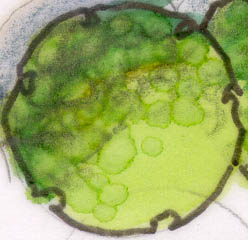
Super Hatch is a very powerful command that enables you to create hatch patterns from images, blocks, Xrefs and wipeouts. This command has many options that are well worth getting to know but for now we will just look at how to create a hatch pattern from an image.

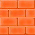
You can create a hatch pattern from any image that AutoCAD can attach. However, if you want your hatch to look uniform, you will need to use an image that will tile seamlessly rather like the tiles that you use for your Windows wallpaper. If you would like to follow this tutorial, you can download the brick image on the right. Just right-click on the image and save it to your work folder. The image is called tile.jpg and is a true colour image, as are all JPEGs.
 Before you start the Super Hatch command, draw a circle somewhere within the drawing window. You will use this circle as the hatch boundary. You can use almost any AutoCAD object to form hatch boundaries for Super Hatch. You cannot, however, use Splines although you can use splined polylines.
Start the Super Hatch command and you will be presented with a small dialogue box (shown on the left) that offers a number of options. For the moment, just click on the "Image…" button. We will consider some of the other options and settings later. You should now see the familiar Select Image File dialogue box. Find the tile.jpg file or any file of your choice and then click the "Open" button. When the Image dialogue box appears, make sure that "Insertion point" and "Scale" are both set to "Specify on-screen" and then click the "OK" button.
AutoCAD then prompts from the command line:
Insertion point <0,0>: (pick a point)
Base image size: Width: 1.000000, Height: 1.000000, Millimetres
Specify scale factor <1>: (dynamically scale the image)
Is the placement of this IMAGE acceptable? [Yes/No] <Yes>: ![]()
Selecting visible objects for boundary detection...Done.
Specify an option [Advanced options] <Internal point>: (pick a point within the circle)
Specify an option [Advanced options] <Internal point>: ![]()
Preparing hatch objects for display...
Done.
Use TFRAMES to toggle object frames on and off.
 |
 |
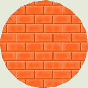 |
| Hatch with Frames | Hatch without Frames | True Colour Hatch without Boundary |
You should now see your image tiled within the circle. Notice that since image frames are turned on, the hatch displays as a matrix of rectangular images. As AutoCAD helpfully suggests, use the Toggle Frames command to turn image frames off. The three illustrations above show the hatch as it first appears (left), with frames turned off (centre) and with the boundary object turned off and colour depth set to True Colour (right).
If you look closely at the images above, you may notice that the hatch does not follow the hatch boundary perfectly. This is particularly noticeable on curved boundaries because Super Hatch uses curve approximations that are composed of straight line segments. You can control how closely Super Hatch approximates curves by changing the "Curve error tolerance" value in the dialogue box. The smaller the value, the more accurate the curve approximation.
Once you have created a hatch pattern using a particular image, you needn't go through the same process of attaching the image next time you want to create a similar hatch pattern in the same drawing. You can copy an existing hatch by using the "Select existing <" button. Make sure that frames are turned on before you use this option because otherwise you won't be able to select the hatch.
Now that you have completed the tutorial, why not try the associated exercise Using Images in order to practice your new skills. Also see Scaling Images to find out how to scale scanned base information.
Tips & Tricks
- Although AutoCAD supports the TIFF image file format, it rather annoyingly does not support TIFFs with LZW compression. If you cannot see the image preview of a TIFF file and it won't display in AutoCAD, the chances are that it has been saved with LZW compression. If this is the case, the only option is to open the image in a raster application such as Adobe Photoshop and save the image without compression.
- For general purpose work, the JPEG file format is probably the most convenient for working with AutoCAD. JPEG images display well in true colour and are relatively small (depending upon the level of compression).
- Try to keep image file sizes as small as possible. AutoCAD will work faster with small image files. When you scan your image, you will need to consider the level of detail required. Don't forget that for many file formats, the physical image size (measured in pixels) is directly related to file size. For example, a BMP image scanned at 300dpi will be 4 times larger than the same image scanned at 150dpi.
- Images do not display when a drawing is rendered.
- If you distribute your AutoCAD drawings by email or on disk, don't forget to send any attached image files along with the drawing file so that those viewing the drawing will also see the images.
Donate to CADTutor
If you found this tutorial useful, you might like to consider making a donation. All content on this site is provided free of charge and we hope to keep it that way. However, running a site like CADTutor does cost money and you can help to improve the service and to guarantee its future by donating a small amount. We guess that you probably wouldn't miss $5.00 but it would make all the difference to us.
Local Navigation
Sponsored Links
The Basics
- Dual Dimensions in a Dim…
- UCSICON Options
- "Best of" Basics: Irreg…
- Tool Palette Basics
- Original Dimension Value
- Possible Solutions to th…
- Avoid Using 'Standard' i…
- Shorten the Plot Scales…
- Update the Source File B…
- User Increment Angles fo…
- Drawing Information
- 'Sign Language'
- Rotate with the Copy Opt…
- Use the INSERT Osnap on…
- To or From the Current L…


