

Using Images
See also, All About Images & Scaling Images
Introduction
This exercise is designed to demonstrate the use of many of the image commands described in the All about Images tutorial. If you have little or no experience of working with images in AutoCAD, it is recommended that you work through the tutorial before attempting the exercise set out below.
 |
Use the QuickFind toolbar at any time to get more information about a particular command.
Step 1 - Sample Data
- Download sample data
- Start AutoCAD
- Display the Reference toolbar
- Open Image.dwg
Before you start this exercise, you need to download the sample image and drawing files. To download the files, right-click on the document icon and select "Save Target As…" from the menu ("Save Link As…" in Netscape Navigator). Save both files in your working folder.
![]() Tree Image.jpg (21KB) - JPEG File
Tree Image.jpg (21KB) - JPEG File
![]() Image.dwg (37KB) - AutoCAD 2000 File
Image.dwg (37KB) - AutoCAD 2000 File
Before continuing with the exercise, start AutoCAD, if you have no already done so, display the Reference toolbar if it is not already on-screen and open the "Image" drawing file. The drawing file shows a garden lawn. During the course of this exercise, you will add some trees to the lawn area and cast some shadows using the Tree Image. Take a look at the final drawing to see where we are headed. You are now ready to proceed to the next step.
Step 2 - Attaching the Image
- Create a new Layer
- Attach Tree Image.jpg
Use the Layers command ![]() to create an new layer called "Tree Image" and set it to be current. This is just good drawing practice and means that the attached images will be on their own layer.
to create an new layer called "Tree Image" and set it to be current. This is just good drawing practice and means that the attached images will be on their own layer.
Next, start the Attach Image command from the Reference toolbar ![]() . When the Select Image File dialogue box appears, find your way to your work folder and select the Tree Image.jpg file.
. When the Select Image File dialogue box appears, find your way to your work folder and select the Tree Image.jpg file.
 |
|
 |
 |
The dialogue box should now look something like the one shown above. To complete the selection, click on the "Open" button. When the Image dialogue box appears, deselect the "Retain Path" option. The dialogue box should now look like the one illustrated below.
Click the "OK" button to proceed, look at the command prompt and follow the command sequence below.
Specify insertion point <0,0>: (pick a point for the lower left-hand corner of the image)
Pick a point in the drawing area to fix the lower-left hand corner of the image. You needn't be too precise at this stage because you can always move the image later.
Base image size: Width: 1.000000, Height: 0.967742, Unitless
Specify scale factor <1>: (scale so that the image is similar in size to the one illustrated)
Move the mouse to scale the image dynamically and pick a point when you are happy with the size.
If necessary, use the move command, Modify![]() Move from the pull-down or
Move from the pull-down or ![]() from the Modify toolbar to move the image into position. Remember, an image is selected by picking on its frame.
from the Modify toolbar to move the image into position. Remember, an image is selected by picking on its frame.
Your drawing should now look something like the one on the right.
Step 3 - Clipping the Image
- Clip the image using the Polygonal option
 |
 |
| Original Image | Polygonal Clip |
Step 3 involves clipping the image in order to hide those parts of the image outside of the tree canopy. The illustration (above right) shows what your image should look like after you have clipped it. Start the Image Clip command from the Reference toolbar, ![]() and then follow the command sequence below.
and then follow the command sequence below.
Command Sequence
Command: IMAGECLIP
Select image to clip: (select the image by picking on its frame)
Enter image clipping option [ON/OFF/Delete/New boundary] <New>: ![]() (default)
(default)
Enter clipping type [Polygonal/Rectangular] <Rectangular>: P (for Polygonal)
Specify first point: (pick a point)
Specify next point or [Undo]: (pick the next point)
Specify next point or [Close/Undo]: (continue to pick points to define the tree canopy)
When you have traced around the tree canopy…
Specify next point or [Close/Undo]: ![]() (or C to close the polygon)
(or C to close the polygon)
When you have completed clipping, your drawing should look something like the one on the right. Remember that if you are not entirely happy with the effect when the clipping is complete, you can always modify the clip frame using grips. Failing that, you can always delete the clipping frame using the "Delete" option and create a new boundary from scratch.
Step 4 - Copy and Scale the Image
- Copy the clipped image
- Scale the new instance down slightly
Use the Copy command, Modify![]() Copy from the pull-down menu or
Copy from the pull-down menu or ![]() from the Modify toolbar to create a copy (a second instance) of the clipped tree image. Place the new image so that it is to the upper-right of the original.
from the Modify toolbar to create a copy (a second instance) of the clipped tree image. Place the new image so that it is to the upper-right of the original.
Next, use the Scale command, Modify![]() Scale from the pull-down or
Scale from the pull-down or ![]() from the Modify toolbar to reduce the size of the second image.
from the Modify toolbar to reduce the size of the second image.
Had the image not been clipped, you could have used grips to scale it dynamically. If you select a clipped image, the grips are used to define the clipping frame rather than the true image frame. However, this does not prevent you from using the right-click options. Both the Copy and the Scale operations could be completed by selecting the image first and then right-clicking. Both Copy and Scale are available from the right-click menu.
When you have completed Step 4, your drawing should look something like the illustration on the right.
Step 5 - Copy both Images
- Copy the two images
 The two images you have already created will be used to form the tree shadows on the final drawing. Step 5 involves copying these two images and placing them over the two originals but slightly to the lower right so that the new images form the tree canopies and the originals cast the "shadow". It is quite important to get this the right way round because new image objects will always hide older image objects when they overlap. Obviously you could remedy any problems with visual hierarchy by using the Display Order options, Tools
![]() Display Order
Display Order![]() Options from the pull-down menu but I have often found them to be unreliable and it is far better to get your object order right rather than have to rely on display order settings.
Options from the pull-down menu but I have often found them to be unreliable and it is far better to get your object order right rather than have to rely on display order settings.
So, use the Copy command again to copy the two images as shown in the illustration on the right.
Step 6 - Adjusting the Shadows
- Reduce the shadow brightness to 35
Use the Image Adjust command to reduce the brightness of the two shadow images to 35 percent. To do this, start the Image Adjust command, ![]() from the reference toolbar, select the two shadow images, and then
from the reference toolbar, select the two shadow images, and then ![]() .
.
 When the Image Adjust dialogue box appears, click and drag the Brightness slider to the left until the value in the edit box reads "35". Alternatively, click in the edit box and enter the value directly.
Notice that, in the Image Adjust dialogue box, when two or more images are selected, the image name above the preview is replaced by "Multiple images". If you try using this command with different images, only the first selected image will display in the preview area.
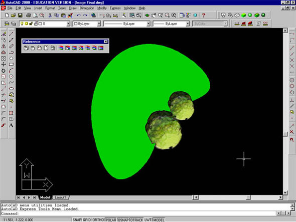
Complete Step 6 by clicking the "OK" button. Your drawing should now look something like the illustration on the right.
Step 7 - Turning off Frames
- Turn off Image Frames
Finally, turn image frames off using the Image Frame command, ![]() from the Reference toolbar.
from the Reference toolbar.
Your completed drawing should now look like the one in the illustration below.
Remember, you can also have your images display in True Colour. See the tutorial All About Images for details. Also see Scaling Images to find out how to scale scanned base information.
Donate to CADTutor
If you found this tutorial useful, you might like to consider making a donation. All content on this site is provided free of charge and we hope to keep it that way. However, running a site like CADTutor does cost money and you can help to improve the service and to guarantee its future by donating a small amount. We guess that you probably wouldn't miss $5.00 but it would make all the difference to us.
Local Navigation
Sponsored Links
The Basics
- Dual Dimensions in a Dim…
- UCSICON Options
- "Best of" Basics: Irreg…
- Tool Palette Basics
- Original Dimension Value
- Possible Solutions to th…
- Avoid Using 'Standard' i…
- Shorten the Plot Scales…
- Update the Source File B…
- User Increment Angles fo…
- Drawing Information
- 'Sign Language'
- Rotate with the Copy Opt…
- Use the INSERT Osnap on…
- To or From the Current L…


