

AutoCAD to Bryce
See also, Importing AutoCAD Meshes
Introduction
Although Bryce does have some 3D modelling tools, they are a little basic. Also, building accurate 3D models in Bryce is difficult. If you need to build an accurate 3D model, you're much better off using an application specifically designed for this purpose such as AutoCAD. Models built in AutoCAD can easily be imported into Bryce where they can be given an appropriate setting. The bonus is that Bryce has a much better renderer than AutoCAD and much better control over materials.
 |
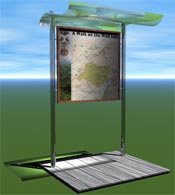 |
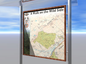
| Model built in AutoCAD | Finished model in Bryce |
This tutorial explains how to take a model built in AutoCAD into Bryce, how to assign materials to the various components of your model,how to use image textures, how to create a simple setting and how to render the resulting scene. Although the key skills shown in this tutorial are directed at the "dressing up" of AutoCAD models, they are also generally applicable to many other situations.
Will any old model do?
Well, sort of. It's true that any 3D model built in AutoCAD can be imported to Bryce but a little finesse and forethought goes a long way.
It's all in the Layers
When you get your model into Bryce, one of the first things you'll want to do is to assign materials to the various parts of the model. So, we need to differentiate the various parts of the model so that each material type can be assigned to a specific object. During the transfer process from AutoCAD to Bryce we get to choose how objects are derived. We can, for example have like for like; in other words, each AutoCAD object becomes a Bryce object. The problem with this approach is that everything gets a bit fiddly, especially with complex models. A better method is to derive objects by layer; all objects on a particular AutoCAD layer will become a single object on arrival in Bryce. This is very convenient as you will see, but it does mean that you need to think carefully about layers before you start.
Layers = Materials
When you build your AutoCAD model, create a new layer for each material type you are using and make sure that objects you want to appear rendered in that material are on the corresponding layer. For example, you might have a layer called "Glass" where all glass objects should be and "Steel" for steel objects, "Wood" for wooden objects etc. The benefit of this is that since each layer becomes a single object in Bryce, you need only assign each material type once and this makes life much easier.
General Overview
Let's start by looking at an overview of the process. The first thing we need is a completed AutoCAD model that has been correctly layered. We'll then export the model to the 3DS file format. The 3DS file can then be imported to Bryce. Once in Bryce, the materials can be assigned and an appropriate setting constructed.
FastTrack AutoCAD to Bryce
OK, maybe you've done this before but you just need a little reminder how the whole thing works. If this is the case, use the FastTrack steps below as a check list. If you have never done this before, the details below should give you a little more information and should help you get a good feeling for what we're about to do during the rest of the tutorial.
Step 1 In AutoCAD, go to File![]() Export… select the 3DS file type and follow the prompts.
Export… select the 3DS file type and follow the prompts.
Step 2 In Bryce, go to File![]() Import Object… and select the 3DS file you just created.
Import Object… and select the 3DS file you just created.
Step 3 When the model appears, land it down. ![]()
Step 4 Ungroup the model. ![]()
Step 5 Use the object edit option to smooth any curved objects. ![]()
Step 6 Assign appropriate materials to the objects. ![]()
Step 7 Add any Image Textures as materials.
Step 8 When you are happy with the appearance of the model, group the objects. ![]()
Step 9 Create a setting by assigning a material to the ground plane and modifying the sky.
Step 10 Render to disk if you want an image of your rendered model, File![]() Render to Disk…
Render to Disk…
The ten step sequence described above works well for all situations where you need to bring an AutoCAD model into Bryce. However, if you want to follow this tutorial closely, you might want to download the sample data in the section below before continuing.
Sample Data
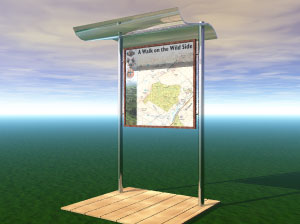
We'll be using two files during this tutorial. The AutoCAD 2000 drawing file is a 3D model of the Information Panel shown in the images above. The JPEG file will be used as an image texture and will be mapped onto the panel.
There are two download options, you can either download the AutoCAD and JPEG files separately or you can download the two together as a compressed Zip file. The Zip file can be uncompressed with a utility such as WinZip.
![]() Information Panel.dwg (112KB) - AutoCAD 2000 File
Information Panel.dwg (112KB) - AutoCAD 2000 File
![]() wild.jpg (35KB) - JPEG Image File
wild.jpg (35KB) - JPEG Image File
![]() atob.zip (51KB) - Compressed Zip File (contains both the above)
atob.zip (51KB) - Compressed Zip File (contains both the above)
Save the downloaded files to your work folder. Now, start AutoCAD and open the Information Panel.dwg file. We're now ready to start.
 Export to 3DS
Select File![]() Export… from the pull-down menu. When the Export Data file dialogue box appears, change the file type to 3D Studio and click the Save button, making sure to check which folder you are saving the file to. By default, exported files are saved to the same folder as the drawing file.
Export… from the pull-down menu. When the Export Data file dialogue box appears, change the file type to 3D Studio and click the Save button, making sure to check which folder you are saving the file to. By default, exported files are saved to the same folder as the drawing file.
You are now prompted to select objects. If you want, you can export part of a drawing using this facility. In this case, we want to export the whole model so select all objects and Enter to complete the selection.
 The 3D Studio File Export Options dialogue box now appears. You can use this dialogue box to control how your AutoCAD objects are converted to 3DS. In most cases, as in this one, there is no need to make any changes. The default settings are just fine but for future reference, it's worth looking at the "Derive 3D Studio Objects From" section. You will see that there are three methods for deriving 3DS objects from your AutoCAD objects. 3DS objects can be derived by layer (the default), by colour or by object. For this exercise, we are using the layer option as discussed above but it's worth knowing that you have other options.
 Click the OK button to save the 3DS file. AutoCAD may take a few moments to do this depending upon the complexity of the objects you are exporting. You now have a version of your AutoCAD model in 3DS format. Close AutoCAD. From this point on, we'll be using Bryce.
 Import to Bryce
Start Bryce and select File![]() Import Object… from the pull-down menu. You will see a file Open dialogue box. Navigate to the folder where you saved the 3DS file. Highlight the file and click the Open button. The model should appear in the center of your work area. The model is automatically selected so it appears highlighted in red.
Import Object… from the pull-down menu. You will see a file Open dialogue box. Navigate to the folder where you saved the 3DS file. Highlight the file and click the Open button. The model should appear in the center of your work area. The model is automatically selected so it appears highlighted in red.
 Land the Model Down
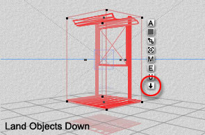
For some reason, Bryce always places imported objects just above the ground plane. This is eccentric rather than annoying because the solution is very simple. You can tell the model is floating above the ground plane because even in wireline view, Bryce objects cast shadows. Just click the Land Object Down icon ![]() and the model will be placed exactly on the ground plane.
and the model will be placed exactly on the ground plane.
 Ungroup the Model
When 3DS files are imported into Bryce, all the separate objects contained in the file are automatically grouped. This is very useful if you want to move or scale a compound object when it arrives. In general it's much easier working with models if they are grouped because there's no chance of the various objects being inadvertently separated. However, in this particular case, we need to have access to the individual objects because we are going to assign materials. We'll regroup the objects later but for now we must ungroup them. To ungroup the model, click on the Ungroup Objects icon ![]() . Initially, not much seems to change because all the various objects are still selected.
. Initially, not much seems to change because all the various objects are still selected.
![]() Click the Time/Selection Palette Toggle in the bottom-right hand corner of the screen to reveal the Selection Palette. This palette can be used to help in making complex selections. For example, you can easily select all objects of a particular type simply by clicking on the appropriate icon. To deselect all objects, click on the small down arrow on the palette and pick "Select None" from the menu. All objects are now deselected and the model turns grey to indicate this. You can now select any of the component objects simply by picking them. Don't forget that you can select multiple objects by shift-clicking.
Click the Time/Selection Palette Toggle in the bottom-right hand corner of the screen to reveal the Selection Palette. This palette can be used to help in making complex selections. For example, you can easily select all objects of a particular type simply by clicking on the appropriate icon. To deselect all objects, click on the small down arrow on the palette and pick "Select None" from the menu. All objects are now deselected and the model turns grey to indicate this. You can now select any of the component objects simply by picking them. Don't forget that you can select multiple objects by shift-clicking.
Note: There are ways to select grouped objects without having to ungroup them first. See Selecting Objects in an Imported Group in the Tips & Tricks section below.
 Smoothing Objects
When 3DS files are imported into Bryce, curved surfaces and solids often appear faceted. This is because objects are converted to meshes and meshes are composed of polygons. To overcome this problem, you can smooth the objects to make them look more like the original.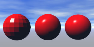 For example, the image on the right shows 3 spheres. The one on the left is an AutoCAD solid sphere imported into Bryce via 3DS. As you can see, the sphere is clearly faceted. The sphere in the middle is an AutoCAD solid sphere after smoothing. The Sphere on the right is a native Bryce sphere. If you compare the middle and right-hand sphere, you can see that the smoothing process is not perfect but in most situations, the difference will not be noticed.
 You can smooth an object by clicking on the Edit Object icon
 ![]() when the object is selected and then clicking the Smooth button.
when the object is selected and then clicking the Smooth button.
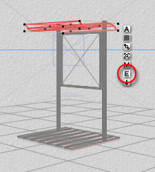
For example, the Information Panel we are working with has a curved roof that needs to be smoothed. Select the roof by clicking it and then click the Edit Object Icon. You should now see the Edit Mesh dialogue box. There are 3 main components to this dialogue box. On the left there is a sliding scale that runs from 0 degrees up to 180 degrees. The default value is set at 85 degrees. To the right of the slider is the smooth button and to the right of that is the unsmooth button. It's a little confusing because the two sphere images are in fact buttons and not preview images.
The slider can be used to control the range of angles that will be smoothed. The default setting of 85 degrees means that all angles up to and including 85 degrees will be smoothed. Angles greater than 85 degrees will not be smoothed. Effectively, the default will smooth anything less than a right angle and in most cases this turns out to be the most common requirement.
 So, to smooth the roof of the Information Panel, leave the slider set to the default value and click on the Smooth button. When you have done this, click the check mark
 ![]() . When you have smoothed the object, you will see no difference in the wireline because Bryce does not add more polygons to the object. Rather, it just interpolates between the existing polygons and this is only apparent when the object is rendered. When you have smoothed the roof, you'll also need to smooth the steel uprights.
. When you have smoothed the object, you will see no difference in the wireline because Bryce does not add more polygons to the object. Rather, it just interpolates between the existing polygons and this is only apparent when the object is rendered. When you have smoothed the roof, you'll also need to smooth the steel uprights.
Note: You may have noticed that there is an option for smoothing exported objects on the 3D Studio File Export Options dialogue box in AutoCAD. You can play about with this setting all you like but it has absolutely no effect on the imported object as it arrives in Bryce.
 Assign Materials
Bryce has some very powerful tools for creating custom materials. Unfortunately, most of them are beyond the scope of this tutorial. We'll assign materials to our Information Panel by choosing some off-the-peg materials from the Material Library.
 As an example, we're going to assign a material called "Standard Glass" to the roof of the Information Panel. Start by selecting the roof, if it is not already selected. Make sure no other objects are selected. Now, click the Edit Material icon
 ![]() to enter the Materials Lab. Initially, the settings in the Materials Lab reflect the current material and at the moment, this is the object colour that was assigned in AutoCAD.
to enter the Materials Lab. Initially, the settings in the Materials Lab reflect the current material and at the moment, this is the object colour that was assigned in AutoCAD.
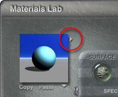
To select a new material from the Materials library, click on the small grey arrow at the top right of the Material Preview Area, shown in the image on the right.
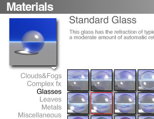 When you get to the Materials library, you will see a list of material types below the Preview Area. Click on "Glasses" and you will be shown a palette displaying a range of glass type materials. The "Standard Glass" material is shown in row 2, column 2 of the palette. Click on the Standard Glass button. When you do this, the Preview Area changes to show the selected material and the button is highlighted in red. Your dialogue should look similar to the one shown on the left.
Click on ![]() just below the palette to return to the Materials Lab. Now click the
just below the palette to return to the Materials Lab. Now click the ![]() button in the Materials Lab to assign the material to the object and return to the drawing.
button in the Materials Lab to assign the material to the object and return to the drawing.
 When you return to the drawing, you should see the new material shown in the Nano Preview at the top left of the screen. It's often difficult to see if a material looks right by using the Nano Preview so you may have to do a render to see the effects of the material in the main work area. You can do this by clicking the large sphere below the Camera Trackball on the Control Panel.
Repeat this process for each of the Information Panel object components. In each case, select an appropriate material from the Material Library. When you are finished, render your model to see a full preview.
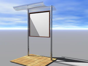
You may notice that in the illustration above, we still haven't got an image displayed on the Panel. That's because we need to use a different procedure to create what's called an Image Texture.
 Using an Image Texture as a Material
Sadly, working with the Materials Lab is not always an intuitive process. However, once you get used to the way things work, it can be a rewarding experience. Keep your wits about you and follow the steps below with reference to the dialogue box image.
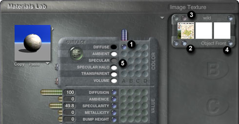
- Click the circular depression at the top of column "A" next to "DIFFUSE". This effectively causes the diffuse element of the material (the colour or texture) to be controlled by "Texture A". You will see a new texture palette appear at the top right of the Materials Lab.
- Click the small "P" (Picture) button. This tells Bryce that Texture A will be defined as an image.
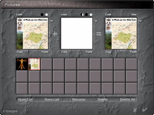 Next, we need to select the image. Click the small button above the P button to go to the Texture Source Editor. In this case, since the texture is defined by an image, you are taken to the Picture Room, where you can select an existing picture or add one of your own. When you get to the Picture Room, you should see at least one picture already there. It's our old friend Leo. Click on the next blank button and using the Open file dialogue, find the wild.jpg file, select it and click on the Open button. You should now see that the image has been added to the blank button and the Picture Room should look like the one shown in the illustration above. Click
  to return to the Materials Lab.
- Now that the image has been assigned as the material texture, we need to tell Bryce how we want the image mapped over the object surface. We can do this by setting the Texture Mapping Mode. The default mode is "Parametric" which means that the image is mapped proportional to the object. Although this works fine for most organic shaped objects, in this particular case, it doesn't give the effect we need. We want the image to be mapped onto the front face of the board. So, click on the Texture Mapping Mode button and select "Object Front" from the drop-down menu.
- We're almost done now but you may find that you need to make some slight adjustments to some of the other material components. In this particular case, a better result can be achieved by changing the colour of the Specularity (the light bouncing off the object) from white to a mid/dark grey. To do this, simply click on the Component Colour icon next to "SPECULAR" and select a colour from the pop-up palette. Effectively, this makes the image clearer by reducing the amount of white light bouncing off the object surface.
When you have completed the five steps above, render the view to get a full preview. You should have something like the illustration shown here. As you can see, the image now looks as though it has been printed directly onto the Panel and that's exactly the effect we wanted.
 Group the Objects
Once all the various changes have been made to the separate objects, it's a good idea to group them so that the whole Information Panel can once again be treated like a single object. This makes working with it much easier.
To group the objects, you must first select them all. The simplest way to do this is by using the Selection Palette. Click on the small down arrow to reveal the Select Options, click on "Select Meshes![]() " to reveal the sub menu and then click on "Select All Meshes". All you need to do now is click the Group Objects icon
" to reveal the sub menu and then click on "Select All Meshes". All you need to do now is click the Group Objects icon ![]() . This makes no obvious visual change to the model but it now acts as a single object rather than a number of separate objects.
. This makes no obvious visual change to the model but it now acts as a single object rather than a number of separate objects.
 Create a Simple Setting
The quickest way to create a simple setting is to assign one of the library materials to the ground plane and then select a sky from the Sky & Fog library.
To assign a material to the ground plane, use the same procedure as in Step 6, above. Click the ground plane to select it and then click the Edit Material icon ![]() . When you get to the Materials Lab, click on the arrow at the top right of the Preview Area to go to the Materials library. You will see that there is a category called "Planes & Terrains" Click on this option and select something suitable from the palette.
. When you get to the Materials Lab, click on the arrow at the top right of the Preview Area to go to the Materials library. You will see that there is a category called "Planes & Terrains" Click on this option and select something suitable from the palette.
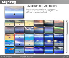
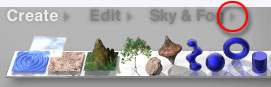 To select an appropriate sky (assuming you're not happy with the default sky) we need to visit the Sky & Fog library. You can go directly to the Sky & Fog library by clicking the arrow to the right of "Sky & Fog" above the toolbar. You are presented with a palette of preset skies. Select one you like the look of and then click
 ![]() to implement the change. You may want to render the scene to see a full preview.
to implement the change. You may want to render the scene to see a full preview.
 Finally, you may want to adjust the position of the sun in order to show the model to best advantage. To do this, click on "Sky & Fog" to flip to the Sky & Fog toolbar. On the right hand side of this toolbar you will see a large black sphere. This is the Sun Control. Click and drag the Sun Control to change the position of the sun in your scene.
 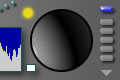 You get instant feedback through the Nano Preview so you can see what effect you are having on the scene. When you are happy with the result, render the scene to see a full preview.
The image below shows just one of an almost infinite number of combinations of ground plane material, sky preset and sun position. With a little bit of experience, you'll soon be able to create realistic looking settings for your models.
 Render to Disk
The final step in this tutorial is to render the scene to disk. There are many reasons why you might want to do this. Maybe you want to add a caption to the image in Photoshop or maybe you want to add the image to a PowerPoint presentation. Whatever, the procedure is the same.
 Select File
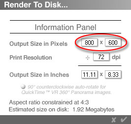
![]() Render to Disk… from the pull-down menu. The Render to Disk dialogue box appears. You will need to think how big you want the image to be. You have the option to enter the size in pixels or in inches. If you are printing the image, you can set the printed size in inches and then set the resolution (the default, 72dpi is probably fine for most purposes). If the image is to de displayed on a computer screen in a web browser or in a PowerPoint presentation, it's more natural to enter the image size in pixels so that you know exactly what you're going to get.
Render to Disk… from the pull-down menu. The Render to Disk dialogue box appears. You will need to think how big you want the image to be. You have the option to enter the size in pixels or in inches. If you are printing the image, you can set the printed size in inches and then set the resolution (the default, 72dpi is probably fine for most purposes). If the image is to de displayed on a computer screen in a web browser or in a PowerPoint presentation, it's more natural to enter the image size in pixels so that you know exactly what you're going to get.
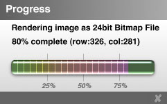
Having entered an appropriate size for the image, click ![]() and you will be presented with the Save As file dialogue box. Using this dialogue you can choose an appropriate file format. Options include BMP, TIFF and PSD (native Photoshop format). Also enter a filename and decide which folder the image will be saved to. Rendering begins when you click on the Save button. A progress bar will appear so that you can estimate how long the render is likely to take. Render time will vary depending upon image size, processor speed and anti-aliasing.
and you will be presented with the Save As file dialogue box. Using this dialogue you can choose an appropriate file format. Options include BMP, TIFF and PSD (native Photoshop format). Also enter a filename and decide which folder the image will be saved to. Rendering begins when you click on the Save button. A progress bar will appear so that you can estimate how long the render is likely to take. Render time will vary depending upon image size, processor speed and anti-aliasing.
Conclusion
We've covered a lot of ground in this tutorial but most of the skills we have learned can be used in other situations. Indeed, things like assigning materials are really basic fundamentals of working with Bryce.
Clearly, Bryce offers much more in the way of materials, atmospherics and render than AutoCAD and the two applications compliment each other very well. If you would like to learn more about Bryce and how it can be used to animate your AutoCAD models, have a look at the Keyframe Animation tutorial.
Tips & Tricks
Save frequently and use Save As
When working with Bryce, it's a good idea to save your work frequently, especially when you come to the end of a particular part of the work process. Unlike AutoCAD, there's no auto save feature, no backup file and no undo history so it's a good idea to save as you work. It's also a good idea to use Save As to create versions of your drawing at different stages of development. This will enable you to go back to previous versions of the project in the event of the whole thing going "pear shaped". Having only one Undo means that it's quite easy to mess things up with no way back so having previous versions to go back to is essential.
Selecting Objects in an Imported Group
 In this tutorial, I have chosen to demonstrate the use of groups and in Step 4 we ungrouped the imported model and in Step 8 we grouped it again after having assigned all the materials. Working with ungrouped models is more intuitive because it is possible to select a component object simply by clicking it and you don't need to remember object names. However, it is also possible to select component objects while they are still part of a group.
![]() There are actually 2 ways of doing this and they are both described below. The first is to use the Selection Palette. If you do not see the selection palette, click on the Time/Selection Palette toggle at the bottom right of the screen. This palette can be used to select any object or group in Bryce.
There are actually 2 ways of doing this and they are both described below. The first is to use the Selection Palette. If you do not see the selection palette, click on the Time/Selection Palette toggle at the bottom right of the screen. This palette can be used to select any object or group in Bryce.
If you need to select a component object of an imported group, click the small down arrow on the Select Palette to reveal the options menu and choose: Select Meshes![]() Mesh Name. The mesh name is derived from the AutoCAD layer name. For example, all objects on the AutoCAD layer "Wood" will become the mesh object called "Wood_1" in Bryce. Obviously, this assumes that we derived objects by layer when creating the 3DS file.
Mesh Name. The mesh name is derived from the AutoCAD layer name. For example, all objects on the AutoCAD layer "Wood" will become the mesh object called "Wood_1" in Bryce. Obviously, this assumes that we derived objects by layer when creating the 3DS file.
Once the object has been selected in this way, you can edit it just as if it were not part of a group. You can assign materials, smooth it and even Resize, Rotate and Reposition it while it remains a part of the group.
Using the selection palette can be a real time saver when you have a complex model to deal with but there is an even quicker way to select component objects of a group (or any other object). If you hold down the Ctrl (control) key on the keyboard when you pick an object, you will be presented with a menu listing all the objects under the cursor. Simply select the object name from the menu to select the object.
Donate to CADTutor
If you found this tutorial useful, you might like to consider making a donation. All content on this site is provided free of charge and we hope to keep it that way. However, running a site like CADTutor does cost money and you can help to improve the service and to guarantee its future by donating a small amount. We guess that you probably wouldn't miss $5.00 but it would make all the difference to us.
Local Navigation
Sponsored Links
The Basics
- Dual Dimensions in a Dim…
- UCSICON Options
- "Best of" Basics: Irreg…
- Tool Palette Basics
- Original Dimension Value
- Possible Solutions to th…
- Avoid Using 'Standard' i…
- Shorten the Plot Scales…
- Update the Source File B…
- User Increment Angles fo…
- Drawing Information
- 'Sign Language'
- Rotate with the Copy Opt…
- Use the INSERT Osnap on…
- To or From the Current L…


