Search the Community
Showing results for tags 'conversion'.
-
Illustrator converted dwg - object colors to layer
Shameless1 posted a topic in AutoLISP, Visual LISP & DCL
I’m a longtime reader and cad user, yet first time poster. I have dabbled with creating list routines in the past but it’s been many years. So, it makes more sense for me to search and inquire with those skilled in the arts of lisp creation and object manipulation. I know Lee Mac has done many fine routines with regard to this, but I can’t quite find what I seek. I routinely receive Illustrator drawings that I must export to ACAD. In Illustrator, objects typically have a Stroke and a Fill. When converted to dwg the resulting file has many objects all on “Layer 1” (some are hatch patterns, most are splines or polylines). Some have true color values (RGB) assigned to the objects, others might be indexed, and still some are set to “by layer”. Sometimes, the resulting objects are in a block in the dwg. I usually explode the block to get to the base elements before processing. I would like a routine that explodes the blocks (nested or otherwise), takes all of the objects based on their color values and moves them to a created layer appropriately named with the value, and color based on the value. Then the objects on the layer set back to “By layer”. Additionally, Hatches to be on layer signified with Hatch in the name, and linework on a layer with Linework in the name. (This is for filtering purposes so I can choose to see only hatches, or only linework) Example layer names: “Hatch – (1)”, “Linework – (1)”, “Hatch – (237 28 38)”, “Linework – (237 28 38)”, Further, Objects with color 0,0,0 are typically white in color and should be set to 255,255,255. Black objects 0,0,1 should be 0,0,0. Purge at the end to remove excess unneeded items. I believe a lisp routine that could do all this should be fairly straightforward to many of the lisp guru’s in here. I am also open to other suggested routines that anyone might know of to aid with processing Illustrator converted dwg’s to streamlined and efficient AutoCAD drawings. I have attached a DWG for reference exported from Illustrator. It also includes an attached Image for reference. Ultimately in the end, I isolate linework. Sometimes convert spline to polylines and then trim away overlapping lines to produce clean outlines and hatches without all the overlapping elements, etc. I cannot be the only person that has sought routines for processing dwg conversions from Illustrator in the timeliest manner. I often spend a great deal of time “cleaning up” these converted files. Thanks for any assistance. TigerHead.dwg- 9 replies
-
- lisp code
- conversion
-
(and 2 more)
Tagged with:
-
Need LISP Function to read text contents and convert ratio to number.
nvoss posted a topic in AutoLISP, Visual LISP & DCL
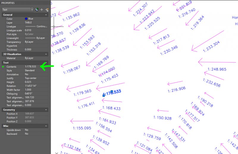
I have a vector map of a floor and all i am given are vectors and grade ratios (i.e. 1:155.095, 1:97.561) of the floor. The problem is that I only want to look at the areas of the floor that are below a certain grade ratio (1:69), but they are ratios set as Text Contents so AutoCAD doesnt understand that these ratios are numbers. I am looking for a Lisp function that, for each text if a ratio across an entire floor (or the layout), copy the text (which is a ratio), find out the number that the ratio is (i.e. take the 1 and divide by 69), then replace the text with just the number (0.0145). I want this to do this for every instance, and there are over 37,000 of these texts on the floor in question. I have attached an image that depicts what I have in the layout. Does anyone know of a lisp function that can do this? -
Hi all! I'm working on drawing a railroad spur in AutoCAD 2011. I had an archaeologist get the measurements for me and unfortunately, she measured in units of 10 (i.e. 1 foot = 10 units so each "unit" = 1 1/4" I'm wondering if there's a way in CAD to automatically convert these units. If I could enter 1 and have it come out automatically as 1 1/4" so that I don't have to convert every single measurement. Any help would be appreciated! Thanks! Emily
- 8 replies
-
- units
- unit conversion
-
(and 3 more)
Tagged with:
-
RGB to ACI colour, can I automatically convert RGB objects to autocad colours?
GMaracchioni posted a topic in AutoCAD LT
Hello there, I have a file (probably exported from rhino, not sure about that though) where all objects have rgb colour properties to them. White lines are RGB 255, 255, 255, which makes them look fine in model space, though they look white on white in paper space. I would like to convert those objects to WHITE, so that I can set a print profile that would make them print black if that makes sense? At the moment I can only select the objects one by one, which is nearly impossible as the drawing is quite big. I tried to use quickselct, which kind of worked, though it did not allow me to select objects belonging to blocks (of which there are plenty, unfortunately!). Thanks a lot for any help! G- 15 replies
-

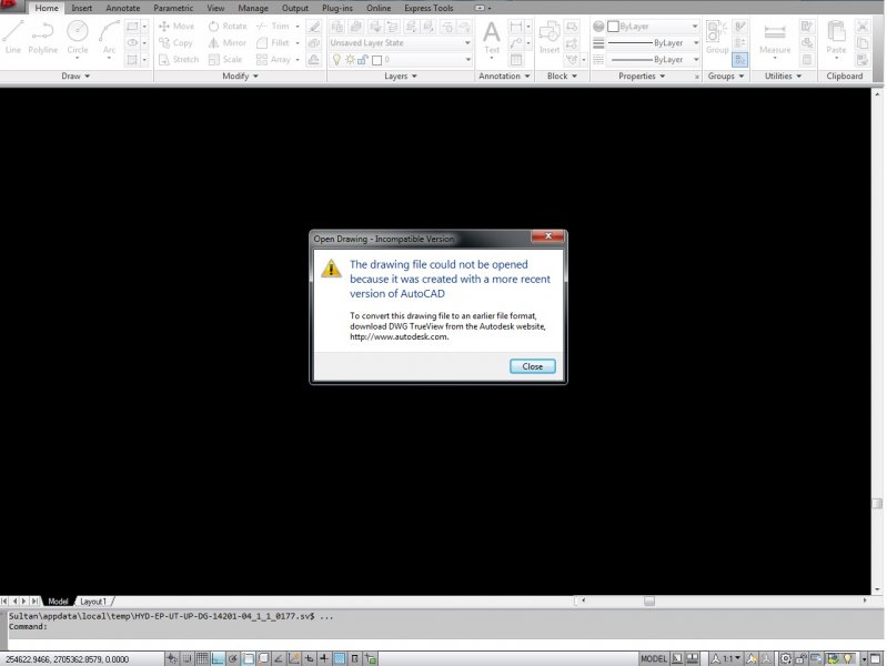
How to convert new version file into old version like AutoCAD2014 into AutoCAD 2007?
tipu_sultane posted a topic in AutoCAD Beginners' Area
Is there any online method to convert file into previous version? If there is no new version of AutoCAD available.- 6 replies
-
- present
- new version
-
(and 3 more)
Tagged with:
-
Best Practice Printing to JPEG (A4 Paper Size)
nicolas posted a topic in AutoCAD Drawing Management & Output
Hi, Would be great if somebody can help me on the best practice to print to JPEG. Paper size is A4. This is for presentation to a blog. Which is best DWG to JPEG by plotting or DWG to PDF then to JPEG? Thanks,-
- jpeg
- conversion
-
(and 1 more)
Tagged with:
-
Hello, I am an architectural archivist - not an architect. I am trying to convert dwg files to IFC. I just export to IFC in AutoCAD 2012. It then creates an IFC file and a log file. The IFC file then doesn't open in AutoCAD. Why is this? Also, this is what the log file says and I'd like to know what this means: [DefaultDomain: ]EXPORT STARTED: 2/17/2014 2:50:27 PM [DefaultDomain: ] ============= Object Count: ============= - AcDbBlockReference : Total: (287) Fail: (287) - AcDbRay : Total: (2) Fail: (2) - AcDbSolid : Total: (4) ** = Object classified as other IFC object. [DefaultDomain: ]EXPORT ENDED: 2/17/2014 2:50:30 PM In addition, under Export, if I select Other Formats, and try to export to IGES or IGS, nothing happens. Why is this? and what is the difference between the two files? Thanks for your help, I am only trying to preserve some architectural history
-
Hi, For an autocad assignment, we have been given a drawing in engineering notation (feet and inches) and have to draw it with SI units dimensions. Doing the drawing was fine, BUT, I drew it in inches and thought that I could change it to millimetres. I have used the units command initially to set up engineering. Then after drawing returned to units to change to decimal. Dimensions turned out in inches regardless. I also tried the scale command to alter the scale, then dimension , still no luck. I went into the annotation menu got to modify primary units and alternate units and still no luck. Could someone please help. Not even my tutorial teacher knows how to do this.
- 2 replies
-
- scale
- drawing size
-
(and 2 more)
Tagged with:
-
This may be a bit complex, so please bear with me. We are a water utility and have thousands of detail drawings of service taps and hydrant connections (maybe 11,000 total). These are in the old Microstation J format. Each drawing is divided into a top half and bottom half. The bottom half of the drawing is the actual drawing portion. The top half of the drawing is text that comes out of an Old Oracle database, into Microsoft Word 2000 through mail merge then is copied and pasted into the top portion of the card. Newer drawings done like this and opened in AutoCAD have the top portion identified as an OLE object (embedded object), while the older drawings just look like a drawing in the top. I'm looking to update the system to ArcGIS and AutoCAD. The data will be moved to a Microsoft Access database (probably later SQL Server), and I want to convert all the old Microstation drawings into an AutoCAD format. ArcGIS will provide the basemap and be linked to the database, with clickable hyperlinks to open the AutoCAD drawings. I would like to be able to keep the bottom drawing half while changing the top half of each drawing to reflect updated data in the database. If this can be automatically updated, that would be awesome. So, I'm looking for a couple things: One is the best program to automatically bulk convert the drawings from Microstation J to AutoCAD (I have 2011). Also, I'm looking for a method to display the text from the database in the top portion of the card using either mail merge with AutoCAD or some automatic method of pulling the info out of the database. Can I just copy-paste this info into AutoCAD as we did with Microstation or is there a better way? Thanks, Nick McNamara GIS Coordinator South Norwalk Electric & Water Norwalk, CT
- 6 replies
-
- mail merge
- database
-
(and 3 more)
Tagged with:
-
I have a lot of maps that have drawing units in yards. I'd like to place points on these maps given their lat/long data. Without having the mapping toolbox is there any way to either convert the map units or convert the points? I'm not worried about spherical distortion as the maps are close in.
-
Convert Wipeout to Polyline Region
LSTLS posted a topic in AutoCAD 2D Drafting, Object Properties & Interface
Hello! Not new to Autocad but new to Cadtutor....I have receive a drawing choc full of wipeouts (arg!). What's worse is the wipeout frames are acting as necessary linework so I cannot just delete them through Qselect. Is there a way to convert wipeouts to polyline regions? They are on many different layers with differing linetypes so I want to retain all those characteristics. Thanks! -
What is the best software program for converting pdf to dwg???


