Search the Community
Showing results for tags 'scale'.
-

Insert a block at multiple points or lines and scale
grouch19 posted a topic in AutoLISP, Visual LISP & DCL
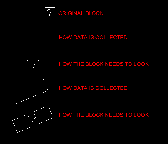
G'day all I'm working on and editing a mapping project from photogrammetry. I have a block which indicates a square manhole cover. (File is attached to this post) My project area has hundreds of these manholes and my client needs each of them scaled and rotated to fit the exact size of the manhole. I had been manually doing this with the help of an ECW image in the background. But the process is rather tedious and not all that accurate. My operators can pick up a three point string showing the height and length of the manhole. Some manholes are square and some are rectangular. I have a few lisp routines that get the block in there. The block insertion point comes in at the first plotted point as required. Is there any similar LISP that will insert the attached block dwg file at the first point collected and scale it based on the 2nd and third point whilst keeping the elevation heights? I've attached two dwg files... One is the block itself and one is a diagram with a better explanation. I've also added a screen shot of what is required. Any help would be appreciated Cheers guys Manhole.dwg BlockSample.dwg
-

Recommendations for plotting to PDF
mickeforsberg posted a topic in AutoCAD Drawing Management & Output
Hello, I was wondering if there are any general recommendations on how to plot to PDF? I'll add some more questions to this. In the Page Setup, what plotter is recommended here? Currently I'm using AutoCAD to PDF (High Quality Print) with paper size ISO A3. But since we are also printing these drawings, and our printer's margins doesn't match the PDF size I have to downscale. And then of course the scale on the printed drawing is incorrect. Should I instead create a new plotter with the correct size specific for our printer? How do you guys do it? -
Hello, I am new in AutoCAD. I draw 1:1 floor plan, I draw 1m in real like 1 in autocad. Now I have to plot it in pdf as 1:50. How can I do that
-
Scale only part of a block, keep the other part a constant size
mickeforsberg posted a topic in The CUI, Hatches, Linetypes, Scripts & Macros
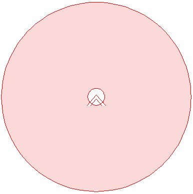
Hello! I'm looking for a solution to my problem. I have a block (center in the attached image) that I'd like to be able to scale as usual, but I want the red circle to remain the same size always. This particular one is a symbol for a smoke detector and the red circle is supposed to be the coverage of this detector. That is why I want the coverage circle to remain a constant diameter of let's say 10 meters, but I'd still like to be able to scale the smoke detector symbol depending on viewport scale. I also want the circle to follow the detector so that I don't have to select both. Other requests are the ability to freeze or turn off visibility of the circle, but I'd still want it to follow the smoke detector if moved. Is any of this doable? What are your thoughts? Thanks!
-

Scaling Problems!?! Model/Paper Space
katherine1992 posted a topic in AutoCAD 2D Drafting, Object Properties & Interface
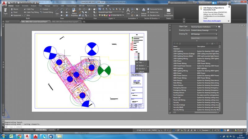
Hi there, I was hoping someone cold help me I am just going through changing the scale of my drawings and for some reason the objects in my model space are now coming up huge in the paper space!? The model space is set to 1:1 I have also gone through and changed all the paper space views with viewports to 1:1 I am really not sure what is wrong I have attached some pictures to make it a little clearer. Any help would be really appreciated
-

Centerlines on Circles - What's popular?
p_burgener@yahoo.com posted a topic in AutoCAD 2D Drafting, Object Properties & Interface
I understand drawing Centerlines on circles got easier with the Centermark tool that came out in R2017. Are people using it? By default it looks like the extensions are a bit small, especially on large circles. Do you simply type Centerexe and raise the value more and more, the bigger the circle is, before placing the Centermark? Do you grip edit all four extensions? Do you change all 4 extension distances within "Properties" (wish I could shift-select all 4 at the same time)? I'd like to have the extensions be exactly 15 percent of the diamter. Can I rig the new Centermark to be proprotional to the diameter? I also notice there are several breaks in the lines when I use Centermark on large circles. Do I need to change the linetype to Continuous within Properties, for each and every Centermark I draw? Background: For decades I've taught students to select the right layer (center, center2, or centerX2), draw a line from 3:00 quadrant to 9:00 quardrant, scale it by 1.3, and then mirror is about a 45 degree line (easy with polar tracking set to 45). If there are too many breaks, I change the layer to one with a "higher" linetype. If all else fails, and there's no LTSCALE that can satisfy all the various diameters of circles (like if the largest circle diameter is greater than 6.9 times the smallest circle diamter), then I "cheap" and assign an Linetype Scale "modifier" within the properties of the largest or the smallest circles. Or am I just getting old and need to get used to the same small extensions and multiple breaks? -

Changing a Scaled Drawing to from 1:100 to 1:1
Funkgonefooey posted a topic in AutoCAD 2D Drafting, Object Properties & Interface
Hi, I am pretty new to AutoCAD. I have a drawing which I need to copy & paste into a new CAD document. It is a base build drawing that has been scaled 1:100 within the model space. I am trying to copy & paste it into a CAD template document however it is not converting the scale 1:1: the scale I want to work in and the selected scaled within the template. Do I need to convert the base build AutoCAD model space to 1:1 and then copy & paste it across? I hope I have made myself clear as it the the first time I am using a forum. Regards, -
This is a very simple one.. I am so inexperienced with writing LSPs. This command adds the current annotative scale for the object. Instead of retyping it I want to assign it to a shorter keyboard shortcut such as "ASA" _AIOBJECTSCALEADD
-
Hey, I am looking to write a lisp routine that, among other things, creates a block and scales it in the x and y but not z (this is a requirement for a coordinate conversion from a client)... I haven't been able to figure it out yet. My thoughts were to add a sort of break in the command where the user can click on the block and change the scales manually, but I don't know how to add such a break. Here's my attempt: (DEFUN C:CC () (COMMAND "_.SCALE" "_ALL" "" '(0 0) 3.28084 "_BLOCK" "1" '(0 0) "_ALL" "" (prompt "change x and y scale of block to 1.025") break "_.explode" ) ) Any help would be appreciated. Thanks, CR
-
Hello! I was learning autocad, and I tried to create a PDF file. Everything drawn was in annotation scale of 1:1 and my units were selected as milimeters. When I opened viewport and selected 1:1 scaling , it zoomed in really much, and it looks like the scaling of 1:1000 in the viewport is the correct one, to have them 1:1 as in drawing and on paper. Why is this happening ? Why isnt 1:1 working as it should?
-

LISP Idea: one-click all changing annotation scales
ryankevin15 posted a topic in AutoLISP, Visual LISP & DCL
....... -
So, I have an Xref Block that when I bring in is way smaller than I want it to be. And I want to scale it up to be the exact same scale as the current drawing. How would I go about it?? ---Thanks to ReMark for showing me how to post a thread.... SMH to myself
-

Dynamic block replacement fails but static block is working
Marcel van Ellen posted a topic in AutoLISP, Visual LISP & DCL
Dear All, I have a problem replacing blocks (titleblock) which is sometimes a dynamic block. When replacing blocks with a new one i get a lselsetp nil error when there is a dynamic block involved. What i try to do is the following: - I try to replace the block by finding it by name (so no manual selection is needed because of a script) - read the coordinates of the old block - read the scale of the old block - delete the block - purge all unused blocks in the drawing - insert the new one in the drawing at the right scale and coordinates The A0KILL does work for static blocks but someone used dynamic ones in our drawings. Now i have to do these blocks by hand for 15000 drawings. Can anyone help me with this issue? (Old blockname is OHTITLE the new one OH-TITLE) (DEFUN C:A0KILL() (setq OHINS (cdr (assoc 10 (entget (ssname (ssget "X" '((2 . "OHTITLE"))) 0))))) (setq OHX (cdr (assoc 41 (entget (ssname (ssget "X" '((2 . "OHTITLE"))) 0))))) (setq ss (ssget "X" '((0 . "INSERT")(2 . "OHTITLE")))) (command "_.erase" ss "") (repeat 3 (command "_.purge" "_B" "*" "_N") ) ; end repeat (command "-insert";Command "K:\\AutoCAD Standaard\\2014\\ALGEMEEN\\Kaders\\Titelh\\Nederlands\\A0\\OH-TITLE.DWG" ;Block Name OHINS OHX "" ) (setq OHINS nil) (setqoh OHX nil) (setq ss nil) ) -

entmake block with attributes, scale and rotation issue
CHLUCFENG posted a topic in AutoLISP, Visual LISP & DCL
I have done quite a search and have not found any good explanation to use entmake to insert a defined block, and scale or rotate that block upon insertion. The idea is to tag a line (pipe), and add the diameter, length, and cut-length of that pipe using attributes. I have the code to get the line information ready, and was working on the entmake for the attribute block to label the "pipes". Here is the code for the attribute block: (defun c:apd (/ LAY1 LAY2 LAY3 LAY4 CLR1 CLR2 CLR3 CLR4 LTP1 LTP2 LTP3 LTP4 FONT value1 value2 value3 rotation p) ;;; Change layer names and colors to suit user. (setq LAY1 "S-Pipe-Detail" LAY2 "S-Pipe-Dia" LAY3 "S-Pipe-Length" LAY4 "S-Pipe-Cut" CLR1 1 CLR2 2 CLR3 3 CLR4 4 LTP1 "Continuous" LTP2 "Continuous" LTP3 "Continuous" LTP4 "Continuous" FONT "Standard" ) ;;;======================== Block Definition ====================== (defun DEF_PipeDetail () ;generated using EntMaker CAB 04- MakeEntmake.lsp (entmake '((0 . "BLOCK") (100 . "AcDbEntity") (67 . 0) (8 . "0") (100 . "AcDbBlockReference") (66 . 1) (2 . "PipeDetail") (10 0.0 0.0 0.0) (70 . 2) ) ) (entmake '((0 . "ATTDEF") (100 . "AcDbEntity") (67 . 0) (8 . "S-Pipe-Dia") (100 . "AcDbText") (10 0.0 0.0 0.0) (40 . 0.095833333333331) (1 . "-DIA-") (50 . 0.0) (41 . 0. (51 . 0.0) (7 . "Standard") (71 . 0) (72 . 1) (100 . "AcDbAttributeDefinition") (280 . 0) (3 . "PIPE DIAMETER:") (2 . "DIA") (70 . 0) (74 . 1) (280 . 0) ) ) (entmake '((0 . "ATTDEF") (100 . "AcDbEntity") (67 . 0) (8 . "S-Pipe-Length") (100 . "AcDbText") (10 0.0 0.0 0.0) (40 . 0.095833333333331) (1 . "-LENGTH-") (50 . 0.0) (41 . 0. (51 . 0.0) (7 . "Standard") (71 . 0) (72 . 1) (100 . "AcDbAttributeDefinition") (280 . 0) (3 . "PIPE LENGTH:") (2 . "PIPELENGTH") (70 . 0) (74 . 3) (280 . 0) ) ) (entmake '((0 . "ATTDEF") (100 . "AcDbEntity") (67 . 0) (8 . "S-Pipe-Cut") (100 . "AcDbText") (10 0.0 0.0 0.0) (40 . 0.095833333333331) (1 . "-LENGTH-") (50 . 0.0) (41 . 0. (51 . 0.0) (7 . "Standard") (71 . 0) (72 . 1) (100 . "AcDbAttributeDefinition") (280 . 0) (3 . "CUT LENGTH:") (2 . "CUTLENGTH") (70 . 0) (74 . 3) (280 . 0) ) ) (entmake '((0 . "ENDBLK") (100 . "AcDbBlockEnd") (8 . "0"))) (princ) ) ; end DEF_PipeDetail ;;;======================== Insert Block ====================== (defun insert_PipeDetail (p lay rot d_lay pl_lay cl_lay font value1 value2 value3) (entmake (list (cons 0 "INSERT") (cons 2 "PipeDetail") (cons 10 p) (cons 8 lay) (cons 66 1) (cons 62 256) (cons 39 0) (cons 6 "BYLAYER") (cons 50 rot);block rotation (radians) ) ) (entmake (list (cons 0 "ATTRIB") (cons 8 d_lay) (cons 10 (mapcar '* (mapcar '+ p '(0.0 0.046875 0.0)) (list (getvar "textsize")(getvar "textsize")(getvar "textsize")))) (cons 11 (mapcar '+ p '(0.0 0.140625 0.0))) (cons 40 (getvar "textsize"));text height (cons 1 Value1) (cons 2 "DIA") (cons 70 0);attr flag (cons 50 0);text rot (cons 41 1);relative x-factor, width ;;; (cons 51 0);oblique angle (default 0) (cons 7 font) ;;; (cons 71 0);text flag (def 0, bkwrd 2, upside dn 4) (cons 74 1);1 BCenter (cons 72 1);1 Center (cons 210 (list 0 0 1));extrusion (def 0,0,1) ;;; (cons 73 0) (cons 62 256);color (bylayer 256) ;;; (cons 39 0);thickness (def 0) (cons 6 "BYLAYER") ) ) (entmake (list (cons 0 "ATTRIB") (cons 8 pl_lay) (cons 10 (mapcar '* (mapcar '+ p '(-0.046875 -0.140625 0.0)) (list (getvar "textsize")(getvar "textsize")(getvar "textsize")))) (cons 11 (mapcar '+ p '(-0.046875 -0.140625 0.0))) (cons 40 (getvar "textsize"));text height (cons 1 Value2) (cons 2 "PIPELENGTH") (cons 70 0);attr flag (cons 50 0);text rot (cons 41 1);relative x-factor, width ;;; (cons 51 0);oblique angle (default 0) (cons 7 font) ;;; (cons 71 0);text flag (def 0, bkwrd 2, upside dn 4) (cons 74 3);3 TCenter (cons 72 1);1 Center (cons 210 (list 0 0 1));extrusion (def 0,0,1) ;;; (cons 73 0) (cons 62 256);color (bylayer 256) ;;; (cons 39 0);thickness (def 0) (cons 6 "BYLAYER");linetype name ) ) (entmake (list (cons 0 "ATTRIB") (cons 8 cl_lay) (cons 10 (mapcar '* (mapcar '+ p '(0.046875 -0.28125 0.0)) (list (getvar "textsize")(getvar "textsize")(getvar "textsize")))) (cons 11 (mapcar '+ p '(0.046875 -0.28125 0.0))) (cons 40 (getvar "textsize"));text height (cons 1 Value3) (cons 2 "CUTLENGTH") (cons 70 0);attr flag (cons 50 0);text rot (cons 41 1);relative x-factor, width ;;; (cons 51 0);oblique angle (default 0) (cons 7 font) ;;; (cons 71 0);text flag (def 0, bkwrd 2, upside dn 4) (cons 74 3);3 TCenter (cons 72 1);1 Center (cons 210 (list 0 0 1));extrusion (def 0,0,1) ;;; (cons 73 0) (cons 62 256);color (bylayer 256) ;;; (cons 39 0);thickness (def 0) (cons 6 "BYLAYER");linetype name ) ) (entmake (list (cons 0 "SEQEND") (cons 8 lay) ) ) ) ;;;======================== Make Layers ====================== (defun make_layer (MyLayer MyColor MyLtype) (entmake (list (cons 0 "LAYER") (cons 100 "AcDbSymbolTableRecord") (cons 100 "AcDbLayerTableRecord") (cons 2 MyLayer) (cons 6 MyLtype) (cons 62 MyColor) (cons 70 0) ) ) ) ;;;======================== Main Function ======================= (if (not (tblsearch "layer" LAY1)) (make_layer LAY1 CLR1 LTP1) ) (if (not (tblsearch "layer" LAY2)) (make_layer LAY2 CLR2 LTP2) ) (if (not (tblsearch "layer" LAY3)) (make_layer LAY3 CLR3 LTP3) ) (if (not (tblsearch "layer" LAY4)) (make_layer LAY4 CLR4 LTP4) ) (if (not (tblsearch "block" "PipeDetail")) (DEF_PipeDetail) ) ;;; temporary setq (setq value1 "MyDiameter" value2 "MyLength" value3 "MyCut" rotation 1.5708 ) ;;; end temporary setq (setvar "osmode" 512) (while (setq p (getpoint "\nPick insertion point >> ")) (insert_PipeDetail p LAY1 rotation LAY2 LAY3 LAY4 FONT value1 value2 value3) ) ;;;end while (princ) ) This code works, but I cannot get the lower two attributes to offset from the line (by half the text height), nor can I get the entire block to rotate (I used rotation 1.5708, or 90 degrees). If anyone can enlighten me, or kick me in the right direction it would be much appreciated. Thanks, CHL -
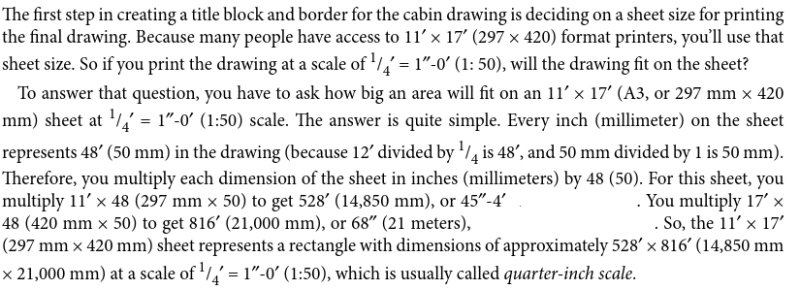
Dear Forum, I'm new to using ACAD so please excuse me if my question seems to be simple. I would appreciate if someone can explain to me the following excerpt that I got from one of the ebook tutorials that I read. Thank you for your help.
-

Is it possible to scale up Annotaive Dimensions
kashbg posted a topic in AutoCAD 2D Drafting, Object Properties & Interface
When setting up new drawing and using the predefined "Standard" dimension style, the dimensions usually show up in model space very tiny. In Dimstyle, under the Fit tab, if I modify "Use of overall scale of" to lets say 250 instead of 1, then I get the dimensions showing larger and proportionate (arrows, gaps, etc) for the model space drawing. Is it possible to have the same flexibility to do the same for Annotative Dimensions, which would scale up the available preset "Annotative" to show generally larger in paper space. I just want to avoid every time altering the settings for the Annotative Dimensions to lets say text in paper 2mm, arrow ..., etc. -

Scale entire layout with viewports
jkoll66 posted a topic in AutoCAD 2D Drafting, Object Properties & Interface
Hi all, I have a colleague that came to me with a question. He would like to grab everything in a layout and scale it by 1.5X while at the same time having all of the viewports in that layout adjust their scales by 1.5 as well. I don't think there is a way to have AutoCAD automatically do this, but I thought I'd post it in case I'm wrong. Thanks. -
Hi All, I was wondering if there was a lisp routine that would scale an object (like a rectangle) down to a certain scale factor like offset works to where it gets scaled down equally? or maybe I'm missing something with the scale command. if I could get some help on this I would appreciate it. and if its not possible just let me know. Thanks, Brian
-
Hi, my new company are using autocad LT and dim everything in paper space. I have no choice in the matter so am trying to follow procedure. I can see the benefits of it but have had a few errors which is causing me problems. basicially the dimension are not reading the vaule they should. for example I have a drawing with a view port of 1:16 (don't ask) and dimensioned from two points a value of 2400mm. I then continued drawing and at some point have went back and noticed the dim now reads 38,400mm. this is happening often and I can see the relation of the sizes, 2400 x 16 = 38,400mm. this has had me stumped and I started deleting dims and then redoing them and then noticed if I match properties it would go back to 2400mm. I then noticed today that if I select the dim and go to the properties window and "Primary Units" the "dim linear scale" value is "-255.9999" I then changed the value to "1" and then dim corrects itself. I did notice that the value in the properties changed from "1" to "-16" as soon as I type "1" and enter. Now I know that before I print I do a select all, filter rotated dims and change value to "1" this should solve the problem but this feels like a work around and I must be missing something. many thanks for any help. I have search online and have found an answer altho quite a few mentions.
-
Hi all! I'm new to AutoCad, having only done a few small jobs over the last year. Mainly floor plans for planning permission. I've finished the plan and I'm tearing my hair out trying to get it to export to PDF to scale. I've done a few before on A4 and they've been fine. I got the plan to 1:200 scale fine on A4 (weirdly, only when I set the scale to 1:20), but when I went up to A3, the scale was way off. A quick measure gave me a scale of around 1:143. I assumed printing at "actual size" from adobe onto A3 would simply give me a scale of 1:100. This is obviously not the case. This is an urgent job (needed to be completed yesterday!) and I've run out of ideas! Any help would be greatly appreciated.
-
Hi All, Desperate here! I have a three drawings all on the same page at 1:1 scale. I am needing to print these three drawings onto an A3 piece of paper all at different scales. I was wondering how I am able to do this. I have a vague understanding that I need to use viewports? - I have my screen in layout set to three sections, however I am unsure of where to go from here! Really appreciate any help! Thanks
-

Batting disappears after having Acad opened for a few min.
Ankeisme posted a topic in AutoCAD 2D Drafting, Object Properties & Interface
So i was drawing plans and decided to use the batting linetype for the insulation. i decided to stop for the day, saved the whole thing, then opened it the other day. When i opened it the batting was still there (all in the correct linetype scale) but after working in the file for a while the batting was gone and replaced by a regular line. I tried the MSLTSCALE, LTSCALE and all those other commands but it doenst change the line into batting... I'm working on a 2014 Autocad student version. Anyone who knows what to do? -
Hi Guys.. I had drawn my floor plan using inches units in the insertion scale..I also used the floor pla dimensions indicated in the blueprint...ahmm..for example instead of making a 1,300..length of a rectangle ...I made it ..1.3 in my actual drawing....I thought I could just rescale it if I needed to...my problem is I'm using A1 paper for my drawing and I need to scale it to 1:100 in the layout..when I change the standard scale of my viewport to 1:100 the drawing looks too small on the A1 paper...any thoughts of what might be the problem to I have to change my units...or use the -dwgunitscommand Thank you
-
Please give me some keywords to solve the following: I'm using Autocad 2016, and drawing the bluepirnts of a house. Everything is measured in meters, so the unit is set to meter. The plan will be used later to construct a scale model of the house. 1/150th scale model of the original. What I would need: During drawing I'd like to "switch" the whole drawing to 150 times smaller, so all dimensions will be at the size of my scale model where I can measure or edit and then go back to the original size. Now I'm making a copy of everithing to a new file and scale it down by the suitable factor to get the 150 times smaller sizes that will fit to my later model. It is not a powerful way, everytime I change something in my original drawing I need to make a new copy and scale it down again. I hope autocad has a function for this, I've read about associative dimensions but I found it's not what I need. (or just I didn't understand it well) thank you for any ideas
-
Hi guys, Is it possible to specify zoom factor that will show on my monitor same size as will printed on paper? For example: i'm making drawing in 1:100 scale in milimeters, and before printing it i want to make sure that everything is readable. I know that depands on screen resolution, dpi and pixel size.