Search the Community
Showing results for tags 'plotting'.
-
 Hey everyone, I'm a Landscape Architect using CAD and often experience the painful experience of plotting very large sets towards the submittal due date. My most recent set after everything was submitted was 158 pages and 230MB. Remember this is just the Landscape addition to a much much larger set. Something to note that brings me here is that from our last submittal to this one was the difference of about 100MB, but with a relatively minimal amount of actual changes occurring in the drawings. So this brings me to my question. Where did the 100MB come from? This question has two parts: FIRST (PLOT MANAGEMENT): I'd love to hear all of your standard order of operations when it comes to plotting for small file sizes. Are there any particular CAD settings to PDF that can reduce the file size? PDF quality control settings? etc? SECOND (DRAWING MANAGEMENT): Which parts of a CAD drawing end up contributing to the bulk of PDF file size? Do the xrefs attached to drawings have a large effect? Blocks? General overall file size? I feel as if there is a compounding issue that occurs but when there are so many drawings involved in architectural drawing sets it's hard to know where to begin.
 -

Recommendations for plotting to PDF
mickeforsberg posted a topic in AutoCAD Drawing Management & Output
Hello, I was wondering if there are any general recommendations on how to plot to PDF? I'll add some more questions to this. In the Page Setup, what plotter is recommended here? Currently I'm using AutoCAD to PDF (High Quality Print) with paper size ISO A3. But since we are also printing these drawings, and our printer's margins doesn't match the PDF size I have to downscale. And then of course the scale on the printed drawing is incorrect. Should I instead create a new plotter with the correct size specific for our printer? How do you guys do it? -
Hello everyoneI was plotting to pdf and everything was going perfect...suddenly this plotter started to produce .pc3 file instead of .pdf when I choose Adobe PDF as plotter. Anyone knows what's the problem? I'm using Autocad Map 3d 2020 &Adobe Acrobat DC
-
Dear CADers, I have a problem with plotting my drawing. The diagonal lines and the text appears very blurry. The file attached below. I have tried reading the forums, and tried a few things but I am not proficient in AutoCAD and am afraid of messing it up. Thank you in advance! 0925 Kathy big.dwg
-

Export to Adobe Plotting Incorrectly
astellings posted a topic in AutoCAD Drawing Management & Output
Good morning, I am having some challenges with plotting from CAD to Adobe then printing. When I export from CAD to 'AutoCAD PDF (General Documentation).pc3' it exports to a PDF in Adobe. When I open the Adobe file, all layers and lineweights are displayed correctly. However, when I plot, certain items appear to go missing. What is weird is that it is not all items within a lineweight - only portions of the line will go missing (see pieces of road and contours will not plot). I cannot find anything corrupt with the AutoCAD file and there isn't anything standing out in Adobe either. I am not sure if this is an Adobe-specific problem or if it is related to AutoCAD. I have attached the CAD file as well as the PDF file. If anyone has any suggestions, that would be appreciated! Sample Work.dwg Sample Work-Preferred Concept.pdf -

Most of the drawing not showing up when plotting
Guest posted a topic in AutoCAD Bugs, Error Messages & Quirks
Hello CADers! Today I have came upon this problem: I'm trying to export my drawing into PDF, but when I press on the preview, I see that most of the drawing is not represented. the layers are not frozen or turned off. any ideas? also, it looks like i somehow screwed up my monochrome.cdb file. could I download a new one from somewhere? thank you for your time
-
AutoCAD LT 2015, Windows I have detailed a part 1 to 1, used a new layout in paper space. Changed it to Arch 24x36 size. Created a window the full size of the 24x36. Scaled the part to the size in model space so that it would fit it to the full size of the drawing. In the plot setting I selected my printer, made sure that the paper size is 24x36 and that it is printing the layout and 1 to 1. I run a preview and it shows that it is taking up the full print page. When I print it only uses a 1/4 of the page!!! What am I doing wrong please???
-
hello I'm quite new to autocad but I'm slowly learning, anyway I know enough to make a floorplan and etc. The problem is when I plot it to pdf, I know you have to set up the viewport and page set up manager and all the basic stuff. I've done all of that already but when I plot it to pdf at actual size it's always off by like .5 cm ( I use a 1:100 scale) I measure on screen with a triangular scale. I've always had this problem and I thought that it was either my pdf viewer (at 1st I was using mozilla's) so I switched to nitro reader, but nothing was happening it was still not accurate. (also if you ask why I don't use acrobat reader, it's because whenever I try to install it on my desktop all my icons become pdf files and won't open anymore) please help me, It's so frustrating not having accurate dimensions. by the way I use autocad 2013 version.
-
Hi I am currently using Autocad 2015 LT in as a freelance in someones office. We tend to hatch our building outlines in grey solid but when we print the grey comes out as purple. I've been inside the network settings and adjust all sensible options but unfortunately it is still coming out as purple. I assume that the issue is with the plotting settings from the workstation but have limited fire fighting experience with plotting. Please help! Plotter is a Cannon IP760, i have plotted the same drawing from several workstations and altered the screening/ pen styles and in a different version of AutoCAD (2010) which leads me to think the issue is applied to the layout of the drawing of the plotter setting on the network. Any suggestions would be gratefully received
-
First I'll say that currently this is stemming from an HVAC drafter/ designer that just wants to put out some quality drawings in an efficient amount of time with not a lot of hassle - kind of like in AutoCAD. This is also coming from 20+ years CAD experience here so I am not talking out of my arse. From AutoLISP programming to Revit I am a drafter/ designer. Thus far my findings are that Revit is a horrible drafting tool (or plotting tool) IMO. From poor representation of symbology to the far too involved annotation tools it is not worth a penny in the long run. It may have some nice features but if our clients didn't require a RVT model we'd NEVER use it. After using Revit for several years now it still does not impress me. The many steps required to accomplish a simple task (especially regarding display) are simply not worth the time spent especially given the final result. Not too long ago there was an article/ blog about how the production side of generating a 3D model for use in Revit is far more desirable a task to complete inside of AutoCAD MEP so drafting issues/ headaches are minimized & workflow is maximized. The article focused on keeping your efforts outside of the Revit platform for production & ONLY using a RVT file for submittal of your required 3D model at time of turn in. Hopefully there are others doing this already that could assist in reviewing the process here so that others, like myself, can start to be more productive in this unfortunate software program that is currently being shoved down the throat of the industry that we work in. Thanks in advance... I hope. Note: Currently using Revit MEP 14 & 15 as well as AutoCAD MEP 14. Learned CAD on v12 DOS a looooong time ago (ITT Tech) & self taught Revit over the past 5 years.
-
I have 20+ years experience in 2d CAD. Two days ago as I was completing two projects something very strange was going on with my plotting/creating of pdfs. So strange that I am struggling putting it into words. But here goes. I had one drawing open and created a pdf. I saved it in the folder of the project but instead of what was on my screen it was a different image. I re-plotted it again and it was okay. I've discovered now that every pdf I create is 1 image behind. I have to make the pdf twice in order to get the image to match what I'm trying to plot. Please help it's driving me nuts.
-

How to create various scale output of a given image file
coralflame posted a topic in AutoCAD Drawing Management & Output
Hi! I have a 1:50000 jpeg image of a sample map and I wanted to create output images of 1:25000, 1:12500, 1:10000 and 1:5000. How can I do that without sacrificing the quality of the original file? Thank you in advance. -
I was working in LT 2014, everything running just fine since we got this version. Then last night I went to plot to a pdf using "monochrome" like I always have, and now it says "monochrome.ctb (missing)". It's the weirdest thing since it worked literally 5 mins before hand. I went thru the autocad help, but nothing seems to help and the "plot styles" menu selection is greyed out. I looked thru the folders and all the .ctb files seem to be in the correct spot. Any idea why this would happen, and how to fix it? TIA.
-

Read information from drawing and use it in a command string
Taurenis posted a topic in The CUI, Hatches, Linetypes, Scripts & Macros
Dear CAD specialists, is there a way to read information from drawing (e.g. content of a specific text object, content/value of specific attribute or any other object that I can place in a layout) and then put that information in a command string? LISP is not in the range of solutions as: 1) I haven't had time to dig into it 2) I have quite a few LT users who also need to be able to use my solution Simple example of the problem I have an object with a value "5". I would like to draw a polyline with a width equal to that object's value ("5") using a Tool with a command string: ^C^C_PLINE;\width;[read object's value];[read object's value]; The real problem I have created PageSetups for different paper sizes for our plotter as well as for creating PDF and plt files. PageSetups include custom paper sizes. To simplify plotting I have created tools for each paper size with a command string e.g.: for plotter: ^C^Cpreview;-plot;N;;_A3_HP500;HP500_A3_A3.2_A3.1_A3.0.pc3;N;N; for pdf file: ^C^Cpreview;-plot;N;;_A3_DWG to PDF;CP_DWG To PDF.pc3;~;N;y; Explanation ^C^C: cancels all the previous commands preview: leads to print preview so the person can check if drawing is OK -plot: invokes plotting N: is the answer to question whether detailed plot configuration is necessary [empty]: uses default (actice) layout name for layout to be plotted _A3_HP500: is the name of PageSetup HP500_A3_A3.2_A3.1_A3.0.pc3: is the name of output device N: is the answer to question whether to write the plot to a file N; is the answer to question whether to save changes to PageSetup The last question which is answered manually is whether to proceed with plot What I would like to do is create a tool which reads the PageSetup name and output device name from something that I can define along with (or within) a layout. Each layout would contain 6 source objects/fields (plotter/pdf/plt x PageSetup/name of output device). This way I could use one tool for plotting, one for creating pdf file and one for creating plt file disregarding the current paper size The command string would look smt like: ^C^Cpreview;-plot;N;;[value from drawing A1];[value from drawing B1];N;N; -
You must bear with me as I'm pretty much self taught on CAD. One thing which I've never understood is the scaling of linetypes and in my new job I have to use it lots. I draw highways, so the linetypes have to be accurate. My model space is always 1:1, but when I'm plotting at say 1:500 or 1:250, the length of the lines mess up. I've solved this by changing the linetype scale to 2 for 1:500 and 4 for 1:250. I have to do this for every individual line though and I'm not even sure if it's the correct method. Can anybody advise?
-

Color to monochrome issue when plotting in paperspace (CAD 2011)
EJMpurdue posted a topic in AutoCAD Drawing Management & Output
Hello, I'm a newbie to the forum, but have been using CAD for quite some time. I usually plot drawings directly from model space since they don't have to be professional or have title blocks for my job. I guess I have gotten a little rusty at paper space and now I am having a color plotting issue that I am determined to figure out one way or another. My layer colors show up correctly in paper space, but as soon as I do a plot (to pdf or to the printer), everything, other than the raster images I have in the title block become monochrome. I have tried changing the plot styles, even going so far as to set up a new one that seemed like it should have worked, but I'm stumped. I don't know if this is providing enough information, so please feel free to ask additional questions if I need to be more specific about something! Any help is much appreciated! -
My company just switched over to AutoCAD 2014 and for some reason the PUBLISH command is not working, or following through with the printing once we complete the required steps to plot. We are able to select the drawings to be plotted (8"x11" sheets), then successfully bring in our page setup that we created with one of the drawings to be plotted (which we use the same template with the same limits on ALL of our 'drawing templates' we design with. After we hit the PUBLISH button at the bottom it goes into the background and just stays there with no errors or anything After a little while we end up just having to cancel and plot individually. We used TrueView to BatchPlot which is identical to the batchplot(publishing) in ACAD 2014 WITH NO ISSUES! Can someone help me as to why I would possibly be having this hiccup?
-

Best Practice Printing to JPEG (A4 Paper Size)
nicolas posted a topic in AutoCAD Drawing Management & Output
Hi, Would be great if somebody can help me on the best practice to print to JPEG. Paper size is A4. This is for presentation to a blog. Which is best DWG to JPEG by plotting or DWG to PDF then to JPEG? Thanks, -
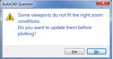
I have been trying to figure out what the connection difference to AutoCAD mechanical the viewports really have. Scenario: We all run 2013 AutoCAD Mechanical. Some users use the ribbon (AMVport) command to create our viewports. Some users use MVIEW. This causes major problems when trying to print through the .pdf program due to the box that comes up: I have figured out how to manipulate the MView viewport enough so that it behaves like AMVport or at least doesn't bring up this box, but now I am finding that the problems exist when trying to use a scale other than Imperial. For instance: I have a detail that is using a scale 1:8. I have two other viewports that are using the scale 1:2 (or 6”:1’0”). I get this message then but only sometimes. It isn't consistent enough to figure out why one will work and why the other won’t. I don’t want to put limits on how the drafters to their jobs, but still have to be able to use the features and programs as they are designed – that includes not having error messages.
-

Problem printing to Canon 755 from AutoCAD
CJJ posted a topic in AutoCAD Drawing Management & Output
Two of my users are having problems printing from AutoCAD Civil 3D 2009 to one of our Canon ipf 755 plotters, I was wondering if someone has had a similar issue or could help me troubleshoot this problem. The users will print their drawing file from AutoCAD and everything looks like it's working. The log file shows that the drawing has sucessfully printed. The print queue for the plotter shows the job in its queue for a short time while it's spooling, then the job clears out as if it had sucessfully printed. But the printer itself never seems to see the file, there are no errors and nothing shows up in the print log. Basically, it seems to me like everything is working fine up until the print server passes the job to the printer, it's like the printer never saw it even though ACAD and the print server seems to think it worked. One user has been experiencing the problem for weeks now, and a second user just brought it to my attention today, saying that it worked fine last Friday. As far as I can tell, nothing has changed on either the print server, printer config files, or his local machine that could affect plotting since then. Both users are on Windows 7 64 bit, using C3D 2009. We have a company print server, printers are pushed through GPO. We use configuration files (pc3) that are stored on a shared network drive, users only have read access to them so nobody can make changes and everyone is using the same configurations. These files work perfectly for dozens of our employees, so far it's only two that seem to be having the issue. Both of them can print from AutoCAD to our other plotters and printers, both of them can print to the Canon from Windows (Test Page, PDF files, etc). It's happening to all DWG files, I don't think it's just a specific file or set of files that aren't working because I've tried printing blank drawings with no luck. Any clues what could be happening? Any ideas to help me troubleshoot this? -

Lineweights won't plot, I've tried EVERYTHING!
Sbeth85 posted a topic in AutoCAD 2D Drafting, Object Properties & Interface
Ok, maybe I haven't tried everything, but that's why I'm here asking your expert advice. ISSUE: I'm dealing with a 3rd party file. They have their own .ctb set up already (I'd prefer .stb, but I don't want to mess with their file). I can't get the lines to print in anything other than Default (which seems to be about 0.2?) Here's what I've tried so far, with no luck: 1. Set the color of my layers on the .ctb to print 0.6 2. Set the color of my layer on the .ctb to "lineweight of the object" and then changed the Layer's Properties (in the layer manager) to 0.6 3. Changed the properties of the lines THEMSELVES to be 0.6!!! 4. I set LWEIGHT to 1 and did "Display Lineweights", but I didn't want the thick lines to appear on the drawing, I just wanted them to PLOT. 5. I've also set PLTSCALE to 1 and MSLTSCALE to 1. I should add that the at the moment I've been printing to a standard office printer, and the lineweights might print if I send the files to a proper print shop, but I'm not sure. Arg, nothing is working... at this point, I've been reduced to doubling lines and filling in with the Solid hatch in order to achieve the thickness I'm looking for... :(any ideas? Any ideas? -

Lineweight issue during plotting / printing - please help!!
wayne783 posted a topic in AutoCAD Drawing Management & Output
I have been using Autocad on my windows laptop for the past 4 years now. LAst month, i purchased the new iMac. I copied my old drawing template and plot styles etc over to my iMac. Heres the problem: When i plot / print a set of plans etc, the lineweights do not come out as clear as what they do on my old laptop. I dont really know how to clearly explain it, but the lineweights almost seem to come out too similar, however they are slightly different. I have gone over the line weights to see if they're all correct and the same as on my laptop, and they are. Im using, and always have been using my canon mx870 printer which is supported both by my laptop and the iMac. Any help would be greatly appreciated, because until then, ill have to carry on using my laptop PLEASE HELLLLLP!!!!!!!!! -
Im trying to plot a 3D object in Autocad 2009 but can't remove the hidden lines. The "Hide" command removes the appropriate lines in the viewport and in the print preview but the print-out still appears with all the lines.
-
Part of my position requires me to upload a PDF of the layout for our floorplans. My question is- How do I make sure the layout stays the same every time? I plot to PDF several times a day and it seems like the second time I plot, the layout goes the opposite direction that I previously setup- under Page Setup Manager... So, I have to start over several times, setting up the layouts when I wish I could just hit plot and go. Does anyone know if there is something I missing or does this happen to anyone else? Is there a save function I am missing here? Thank you!
-

how to prevent new layers (added to model xref by others) being plotted
mvrcad posted a topic in AutoCAD General
Gday all I am trying to help a colleague thats having some hassles. he has a model file that has been xreffed into hundreds of drawings, and now another drafter has added a layer (a screen)over the top of this guys windows. I had a gut feeling reconciling layers had something to do with this, perhaps not. can anybody please help? i suggested that new layers be created and then frozen, and then in any new drawings needing these new layers, the layer can be unfrozen. there must be a better way. Cheers Marcus