Search the Community
Showing results for tags 'electrical'.
Found 17 results
-
Is it possible to automate or make it easier to create a symbols legends in LT? Ideally I would like to create a legend of all the symbols(blocks) used in a drawing and not use our standard legend as all the symbols are not always used.
-
Hello, So the following is an example of a very nice homerun. You can bend it and it'll move the arrow accordingly, reducing time spent drafting during clean up. I'd like to make one similar to the one attached that will allow you to show the wires associated with the circuit. For those not electrically inclined, Long line = neutral Short line = hot/1phase Long line+dot = ground I think it would be nice if you could bend the homerun like the one attached but also be able to change it using a dynamic block type setup where you can chose different circuit types based on what it is powering. Is anyone savy enough with AutoCAD to do something like this? Dynamic Homerun.dwg
-
Hello, could someone make a .lsp for calculating demand amps similar to these two Lisps for adding numbers, and calculating phase balance percentage(%)? They work by selecting a value, hitting space bar to execute the command and then selecting a destination piece of text for the calculation. PhaseBalance.LSP This .lsp would prompt for a demand wattage, and divide by 360 and then prompt the user for destination piece of text. I'd like the amperage to round up to the nearest tens. Thank you in advance.
-

Electrical Panel Phase Balance Calculator LSP Lispertine
ryankevin15 posted a topic in AutoLISP, Visual LISP & DCL
Okay, here's the deal. I need a LISP that calculates phase balance which is basically percent error between two numbers in the following form. However, we need it to take a selection and find the largest number, smallest number and make the following calculation, regardless of the numbers in the set. (Big - Small)/Big * 100 = X.X% Currently, we use an ADD.LSP which takes a selection and adds up the numbers. I am not familiar enough with the programming in order to take this relatively simple arithmetic and make it a working LSP. I have attached the ADD command if anyone is able to do something like this. add.LSP It should work by making a selection, then prompting the user to select where to place the phase balance (By adjusting the selected text to the updated value X.X%). -

Relocation of loads presentation on demolition drawings
sam2001 posted a topic in AutoCAD Beginners' Area
I am working on a project where it involves relocating of some optional stand-by loads to the emergency side. On the demolition electrical oneline drawings when the load is being demoed it is shown as dashed lines with mark up as demolished. How is a load which is not being demoed but re-located or re-fed from a different source on demolition drawing. Similarly how to show it on the floor plan as well. Thanks in advance for any advice. -
Hello Friends, I was wondering if there is a website to look at some sample projects for electrical drawings projects like Index, symbols, panel schedules, cable schedules, onelines, demolition oneline etc
-
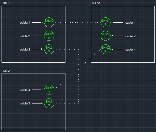
Hello Guys, I wish to all a good new year!!!... I was looking to any Lisp to help doing a Cable Interconnection Address Link, working with a interconnection drawing to electrical system we have to link one cable from one page (eg. sheet 1) to another (eg. sheet 2) on the same dwg file (in other cases in diferente dwg files - one sheet by file drawing). Someone knows some lisp that can do a sheet and a item address link as the file attached? Automatically, selecting the first point to link with the second point, presenting on the first point the end address (sheet and item), on the other side the source (sheet and item)? Thanks in advance!!!... * Item is a order of item on the specific source sheet (without repeat).

-
Is it possible when Activating a project in Autocad Electrical to run a customized script or macro? Specifically, it would be nice to set the "DefaultFormatForSave" variable to the proper customer specified value. Thanks in advance
-
Which program was used to create this? how do i create something like this for a pv system design?
-

Electrical Wiring Diagram
naruto2021 posted a topic in AutoCAD 2D Drafting, Object Properties & Interface
I need to make an Electrical Wiring Diagram of an Induction Furnace. But i'm new in autocad, and i'm not really sure it can be done easily with autocad. All help is welcome. I'm working making in the maintance of this equipment on my university. Here is my mail: naruto2021@gmail.com https://www.dropbox.com/s/wa1sollj2u91zeb/P1020563.JPG https://www.dropbox.com/s/chq02guawmjl2pk/P1020564.JPG https://www.dropbox.com/s/hiz1wc3fyauw9h7/P1020565.JPG https://www.dropbox.com/s/blckc6adkle8wcp/P1020566.JPG https://www.dropbox.com/s/5yospmtv17vw2vr/P1020567.JPG -

Custom title block/border to line up with ACADE co-ordinate system
griff_nz posted a topic in Electrical
Hi there I am trying to create custom borders with x and y co-ordinates, but am having trouble lining it up with the ACADE co-ordinate system. Any ideas out there? I can use an existing template and change fonts etc but what if I wanted to squeeze up the axis or use different reference characters ie. Alpha-numeric instead of numeric-numeric? It may be an easy one for the more experienced out there!!! -
So I've been toying around with AutoCAD Electrical 2013 for a couple weeks now. I've been trying to figure out a way to adapt it to create P&ID drawings. There seems to be a lot more setup work involved but for now I've been mainly trying to convert my custom P&ID symbols to ACADE symbols using Symbol Builder. I thought I had the basics figured out until I inserted the first said blocks from the Icon Menu dialog box. The original block turned component symbol now shows all of the wire connection attribute grips when selected instead of just the insertion point grip. I have no idea what went wrong. I should note that these blocks also have dynamic attributes like flip, scale, and visibility. I've looked around on the web, through the ACAD help, and did a couple searches here to find a similar problem to no avail. Anyone have any insight into this issue? These kinds of issues make me wish the "higher up's" had listened when I said we need to switch to P&ID but that's a whole other issue I won't get into here...
-

Edit standard blocks and symbols (MEP 2012)
sinbad92 posted a topic in AutoCAD Drawing Management & Output
Hey I am struggling to edit the standard set of blocks that comes with AutoCAD such as receptacles junction boxes etc. I want to edit the standard blocks and then save my changes for future use. Right now the blocks come in at different sizes then I would like. I try to edit them in the block editor however the changes I make do not apply to any other or new drawings that I make. Please help me, any and all help would be hugely appreciated! Thank you! I have attached an image of the differing symbols and sizes. I want them to be consistently sized.
-
Hey guys! I have always come here for answers to my Lisping needs, but now I need to request some help with a Lisp I have been working on for a few days. I created this program that allows you to draw electrical circuits with choices of exposed/concealed conduit, homerun/full run, number/type of wires in circuit, etc. I have the input, wiring and block creation down, but now I just need to figure out how to insert and align the symbols for the different wires along anything curved. The closest program I can find to what I need is LeeMac's Object Align routine, however, it only allows you to select objects as a whole and align the whole to the line, not the individual objects aligned to the curve like you see on electrical wiring plans. I love the preview stuff of LeeMac's program, just need a version where the individual objects are aligned separately as shown in the below images. Lee's: What I need it to look like: LeeMac, is there perhaps a way you could incorporate this into your code as an option to align objects individually at their insertion points? Right now, my code prompts for a point to draw all of the symbols used and the number of them in a straight line. I could then use this updated program to select those symbols and align them to whatever curve I needed too The absolute best way would be to adjust my original code so that after you draw your circuit lines, it shows a live dynamic preview of all the symbols used aligned at their basepoints along the line you want to put them on. But maybe that would be for another day... Unless LeeMac, you would like to check out my code and tweak as needed... ****EDIT**** I figure I might as well go ahead and post up what I have so far. It is working pretty good, except that the first time I choose how many of each to use, it doesn't space the blocks correctly, but then it will afterward. Perhaps people can see what direction I am taking this and offer ideas or improvements to the code to make it work better? MEP Design.zip
-
Hi all. My company is fairly large for an electrical contractor, and we're all over the board in CAD experience. We have people that started as hand drafters back before computers (and STILL prefer hand Drafting over CAD or 3D CAD or even BIM), and we also have a couple proficient in BIM, and everyone else in between. We have been using AMEP for about 4 years now, but I can say that the only functions we've used on a regular basis were Conduit & Cable Tray, and NOTHING else. We've coordinated with other trades using Navisworks Manage for Collision Detection Analysis, but that's about as far as we've gone. For the past few weeks I've been exploring AutoCAD MEP and all of the other features it has to offer, and I must say I love it. Plus, it seems pretty powerful and flexible, and a great migration step to working in Revit MEP. However, not many of our jobs that are coming in use or require AMEP, let alone Revit. So my question to you all is, which software or Suite is best. Keep in mind we typically receive files from an Architect or Engineer in 2D format, receptacles are blocks (not Devices), etc. I would like to try to find some justification for moving MEP, but at the same time the more I think about it, the more I come to realize that as a contractor, it might not be worth it where 80% of the jobs we do are post-Engineer-Design. Of course on jobs that we're the Engineer, that's totally different, I would definitely try to use AMEP where applicable. Or even if the Arch/Eng firms provide us with all files necessary (APJ files, EPD files, etc), we could use that. Are there any Electrical Contractors out there on the same boat that could share their experience with the capabilities of AMEP or even Revit MEP.
-
If you vertical product users wouldn't mind, could you send me a small sample DWG file created with a vertical product (except Civil 3D - I have plenty). Just a small sample drawing that contains some objects specific to the vertical product. Thanks. rkmcswain__at__yahoo__dot_com
-
Hi all New to this forum and am in search of help. I have been lumbered with a project to take ACAD drawings of a control system into ACAD Electrical. The old version has no use of layers and has text for the wire numbers. What I would like to do is change the text lines to a wire layer thus giving me use of the auto numbering. Additionally I note that the export to spreadsheet does not take all of the attributes of the components i.e. a relay contact shows, when editing the properties, the wire number at each connection but is not in the spread sheet. This woudl be great if it could report this to produce the wiring schedule automatically. So to sum it up is tere anyway to get a lisp progran to change the text object and can it also extract the data I need for the wiring schedule into any form of text file. Cheers Phil