Search the Community
Showing results for tags 'text'.
-

Put mass selected integers in ascending order starting from a given integer
tsotzo posted a topic in AutoLISP, Visual LISP & DCL
Hello, Let's say we have a group of integers as text in dwg. How would we put them in in ascending order by one(+1) starting from a given integer? Let me give an example to make it clear. Let's say we have the texts 1 2 5 5 5 8 9 11 11 15 and the given start integer is 6. We select them all together and the range in selection set is random. Let's say 5 2 8 15 1 5 5 11 9 11. Now, we want to put them in ascending order by one starting from number 6 replacing the "old" range with the new. In the end we must have this: 6 7 8 8 8 9 10 11 11 12. That is 6(in place of 1), 7(in place of 2), 8(5), 8(5), 8(5), 9(, 10(9), 11(11), 11(11), 12(15). I hope it is clear. How would we do that in an efficient way? Thank you in advance, Kostas -
I am so close to getting this code to perform but need some final touches and manipulaton.. Currently it offsets all text on a specific layer and copy's and moves it up "0.15" which is what we already have doing with another layer we use in our drawings. (we use this to add specific descriptions above a labeled point.) What I am looking for now is to change the code so that instead of offseting/copying/moving every string of text on DEFICIENCY layer within the drawing, I would like for it to prompt me which individual string of text I would like to offset - i.e. ("\nSelect Text to Offset: "), THEN after I make that selection it offset/copy/move that string up "0.15" and be put on DEFICIENCY layer with its respective properties... Hoping someone can chime in soon and thank you all for the support!
-
I regularly use text to number objects for designating cut order. In the past, I have cobbled together some code that can quickly increment or decrement all selected numerical text in case I make a mistake and/or have to change something. This works marvelously, but often, I find that I need to go beyond that and completely reverse the order. Using this code as a starting point, I thought this would be super simple but the fact that I'm trying to do list manipulation to text objects is completely throwing me off. I'm still a bit new to this sort of thing. I was thinking I'd get a list of all selected text, sort it, then reverse that list before applying changes to the text. Highest number gets swapped with the lowest, second highest with second lowest, etc. ("1" "2") would become ("2" "1") ("2" "1" "4" "5" "3") would become ("4" "5" "2" "1" "3") ("2" "8" "17" "4") would become ("17" "4" "2" "8") ("3" "5" "-4") would become ("3" "-4" "5") I'm not sure where to start, nor what process to use. My main problem is that I can't figure out how to sort and edit the data without losing links to the correct text objects. Any help would be awesome. Here is the my quick increment/decrement routine that I'm trying to start with. ;Quick Increment/decrement ;Increments/decrements all selected text integers by 1 ;I hacked this code together with help from an "increment in range" routine. ;Original code can be found here https://forums.autodesk.com/t5/visual-lisp-autolisp-and-general/incriment-numbered-text/td-p/3614646?nobounce ;Quick Increment (defun C:qi (/ textselection textobject old) (vl-load-com) (setq textselection (ssget '((0 . "TEXT")))) (repeat (sslength textselection) (setq textobject (vlax-ename->vla-object (ssname textselection 0)) old (vla-get-TextString textobject); initial text content ); setq (if (and (= (strlen old) (strlen (itoa (atoi old)))); text represents integer ; Blocks e.g. "12A", "4.5", "C37", and completely non-numerical ; text [except for next test], but allows negative integers. ; Also disallows e.g. "06", "008", so if those should be included... (if (= (strlen old) 1) (wcmatch old "#") T) ; blocks single non-numerical character e.g. "A" [passes prior test] ); and (vla-put-TextString textobject (itoa (+ (atoi old) 1))); replace ); if (ssdel (ssname textselection 0) textselection) ); repeat (princ) (setq sel1 (ssget "P")) (sssetfirst nil sel1) ); defun ;Quick decrement (defun C:qd (/ textselection textobject old) (vl-load-com) (setq textselection (ssget '((0 . "TEXT")))) (repeat (sslength textselection) (setq textobject (vlax-ename->vla-object (ssname textselection 0)) old (vla-get-TextString textobject); initial text content ); setq (if (and (= (strlen old) (strlen (itoa (atoi old)))); text represents integer ; Blocks e.g. "12A", "4.5", "C37", and completely non-numerical ; text [except for next test], but allows negative integers. ; Also disallows e.g. "06", "008", so if those should be included... (if (= (strlen old) 1) (wcmatch old "#") T) ; blocks single non-numerical character e.g. "A" [passes prior test] ); and (vla-put-TextString textobject (itoa (- (atoi old) 1))); replace ); if (ssdel (ssname textselection 0) textselection) ); repeat (princ) (setq sel1 (ssget "P")) (sssetfirst nil sel1) ); defun
-
Hi, I have a 3D point (X,Y,Z) and label. This point and label have the same 2D base point (Xp,Yp = Xl, Yl). And there is not a block. Is it possible to export point number and coordinates to text file (with space as separator)? I attached image with an example. Thanks for any assistance.

-
Is there a command or a LISP (I have checked out LEE's but to no avail from what I found) that I can run say that will allow me to select text and then select a line and it be parallel with it? I know the command TEXT ALIGN but this doens't do what I am looking for, that, or I just don't know how to properly run the command? Any who, as always, thank you for any and all input. Miller
-

Upside Down Text When I Plot To PDF
mapwhisper posted a topic in AutoCAD Drawing Management & Output
Has anyone seen or head of this error before, and does anyone have any suggestions on how to stop it happening. It does seem to be a random occurrence. When I plot to PDF the letters are coming in rotated about 90 degrees. No Idea why.
-
 I'm about to receive a bunch of borehole data for a bigger project with x,y coordinates in state plane for each hole and I believe it will be sent as an Excel file. I'd like to add a center-justified text consisting of the borehole name at the x,y coordinate where it should go so I can quickly check out the location of a hole and then look up its other properties by name in the Excel sheet. So far, I'm thinking about concatenating the cells and adding spaces in a separate column in excel so that for each hole I have something like: text j mc 0 x-coordinate,y-coordinate BH120 in a single cell. That way I can copy and paste that line at the CAD command prompt and skip a ton of key strokes going through the text options. I've done a similar workaround, inspired by someone here on the forums, when working with line segments where clients have sent me endpoints in Excel format. It's been great because it's transparent enough that I can forward my spreadsheet on to any one of my coworkers and have them duplicate the process without having to worry about a couple of people in my work group who only have LT and can't use LISPs (I think?). The difference is that while you can exit a line command by putting a space after that entry above, I think the only way to end the text command might be by pressing enter twice and I don't know if there's a way to just concatenate a couple of enters at the end of a line like I can a couple of spaces. The question is, is there a quick cheat that would let me do everything by copying and pasting multiple lines formatted as above all at once from excel without having to press enter after each hole? Is there an arraypath type command that's more well-suited to this instead, since I do have x,y coordinates?
 -

Change a specific TAG within a block of a drawing
noslenac posted a topic in AutoLISP, Visual LISP & DCL
I've been trying to find existing lisp routines to do the following for a while now (off and on). While I have found some that will change values of Attributes or the text width for every piece of text in a drawing, that is not what I need done. I need a lisp routine that will be manually modified with the current Attribute TAG and Block name based on client titleblock. It can't require manual selection (user input) as this will be used in a script to batch run the lisp routine. To kind of summarize, I would like the ability to specify a block name and attribute tag name (in the specified block) and be able to set the text width factor in the drawing to account for longer filenames per client requests. This is only for the 1 attribute in all drawings. Any help will be greatly appreciated. Here is an example: Titleblock has: Attribute: File name TAG: DRAWINGNO Value: Linked to actual filename with a field Current text width factor is .8 and it needs to be .7 to fit within the titleblock space. -
 HI THERE! AUTOLISP FOR Copy of data from excel to acad.xlsxIN TEXT 90DEG ROTATED, NEED A AUTOLISP THAT CAN FUNCTION TO CREATE PARTIAL DISTANCES(0.000.000), CUMULATIVE DISTANCE(0+000.000) BASED ON THE LENGTH BETWEEN THE EACH VERTEX OF THE POLYLINE (APPROX. 3.69KM), PLEASE FIND THE ATTACHED DRAWING, THANKS IN ADVANCE PLEASE HELP, CREATE A LISP FOR PL.dwg
 -

Extract Text data at a XYZ coordinate from Autocad
kArThIcK posted a topic in AutoLISP, Visual LISP & DCL
Hi guys, Attachment: Test Drawing.dwg I want to retrive the text's content, the text is placed at a certain XYZ co-ordinate in Autocad, (same coordinates, always for all the drawings). [Refering to the attachment]: The text below the "Surface Area" and the "Weight", are mostly the texts i'm trying to get. These texts sometimes come as a single line text or as a mtext or within blocks.. but always they appear at the same coodinates. Can somebody help me with this? -

Draw polyline and write text above/under/near with lenght
hjsolf posted a topic in AutoCAD Beginners' Area
Hello. I'm looking for a way to draw a polyline, where i enter the points with mouse clicking and when i click the final point and enter button, it writes in text the total lenght of polyline. I know that i can go to the properties and see the total lenght of the polyline and then i can use mtext to write that value near my polyline, but because i have to do that more than 1000s times, i was wondering if there is a faster way or a lisp routine. All ideas are welcome. P.S. I'm using Autocad 2009 and i'm beginner/medium user. Thank you -

Lisp to create numbered folders based on selection
benhubel posted a topic in AutoLISP, Visual LISP & DCL
I have some drawings which contain hundreds of numbers (example: 1-218b), each of which is on geometry which will be written as a block into its own folder. I am trying to write a Lisp that will create all of the folders based on the selected text. I have found a few posts about writing a directory, but it's all super confusing to me. General routine process: 1. Get selected text objects 2. Prompt for directory to create new folders in 3. Create a folder for each selected text object, named based on the text It's ok to assume that the text is already selected when the Lisp starts. If no text is selected, I'd just send an error message to the console and end the routine. It's preferable that the directory prompt is GUI based so that I can navigate to the directory, but I am absolutely clueless here. If needed, I can just copy and paste the directory path into the console. The routine doesn't have to work with MText. The files contain only single line text. If I can get any code working, I'll post it, but I think it's going to take a good long while. -
Hello I would like to have a simple lisp routine that divide all the numbers in a given layer by 20, can anybody help me? Thx
-

Rotating multiple objects / text in 3d around their insertion point
tmduk posted a topic in AutoLISP, Visual LISP & DCL
Hi there all First post and it's a request for help (although been a long time lurker) I've got a 3d drawing that has a load of levels in 3d positions with text displaying the height value. These are all orientated and readable in plan view. I want to create some sections using the 3d information, and what I would like to work out is the best way to manipulate the level cross (block) and associated text so that it is rotated to a side on section view. (in model space not just in a paper space viewport) I've tried using the rotate3d command on mass and can't quite get the results I'm after, basically it rotates the text so that it is now readable in the section but when selecting multiple items it rotates the whole lot around one datum rather than rotating each item around it's own insertion / justification point. in the above image, to the left is what I'm starting with levels (red) in 3d - next is the result I get from using the command rotate3d (levels in white) when they are selected in one go. the text is rotated so that it's legible but has moved away from the 3d polyline - the 2 to the right show what i'm aiming for, having manually moved them to their representative points and then rotated, however there's gonna be quite a few to rotate and shift along different sections, so it would be good to have this a bit more automated any suggestions? am I not using rotate3d to it's full potential or is this something that would need to be solved with a lisp routine? picking a temp ucs along the section line and then selecting the relative objects to rotate thanks in advance -
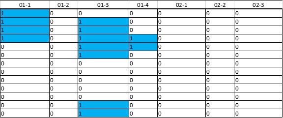
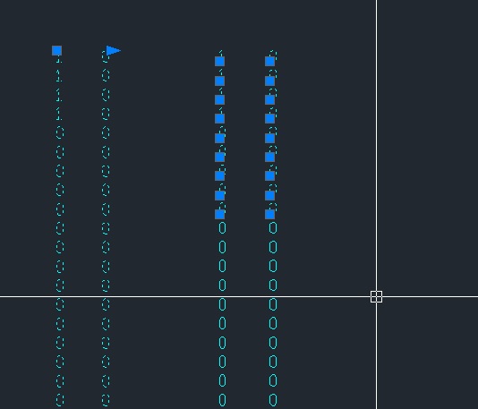
Currently, I have an Excel table. Numbers of column contains 0 or 1. I have to copy column by column into notepad and then copy the notepad contain to CAD. After that, I have serval individual column of Mtext. Then I further explode them into text. A numbers of individual text are pasted on CAD and this is what I want. However, if I do copy multiple column into notepad, the result is a whole Mtext which is containing all columns. I explode the Mtext and I will obtain multiple line of text. I am searching for a lisp to convert/separate Mtext to individual text. For more advance, I want these 1 and 0 located in different destination point from excel to CAD by a lisp.
-
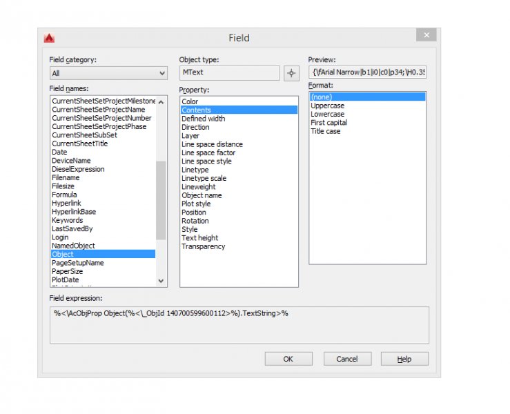
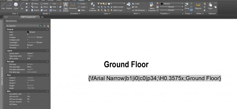
Hi I am trying to get a field to link two texts, so that when the first is edited, the second updates to the same, similar to the =CELL function in excel. I can get this to work when using standard text, however when I try to do this with text that is bold and Arial Narrow, the second text displays lots of additional information. I have attached a screen grab of the field window to show what I mean. How can I avoid this? I am working on AutoCAD LT 2016.
-
Hi I am new to using fields, and I am having an issue. I wish to link two mtexts, so when the first is edited, the second updates to display the same text, similar to the =CELL function in excel. I use Field>Object>no format, yet it displays to complete contents, including font etc. How can I get the second text to simply display what is in the first text. I have attached a screenshot of my issue. Any suggestions gratefully received. Thanks
-

How do I display RL (Reduced Level) of points in autoCAD ?
MrD33P posted a topic in AutoCAD Beginners' Area
lets say I have a drawing of tower and I need to display levels at different heights, say, one at base and then at 1.5 meters above and then at 3 meters .. RLs of these points is 272.5, 274, 277 etc. (RL means height of point above mean sea level). Is there any way to do it fast than just using text command, since I have to display several RLs in one drawing and I have several such drawings. please guide me. -

Text box that will increase or decrease in length with text
JamFam posted a topic in AutoCAD Drawing Management & Output
I want to be able to create a dynamic block that I can insert into my architectural drawings. This block will contain text with a box around it. The box will lengthen or shrink depending upon the length of text. Better still, regardless of the text size, the text box will automatically resize depending upon the amount of text AND the size of font. Thanks -
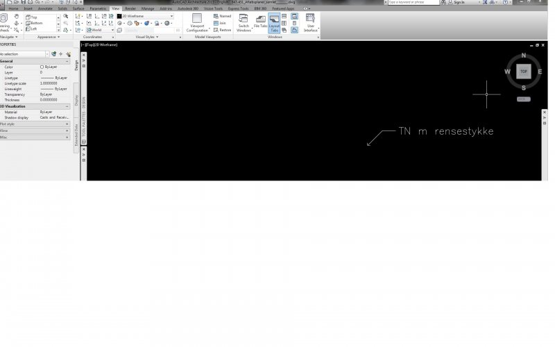
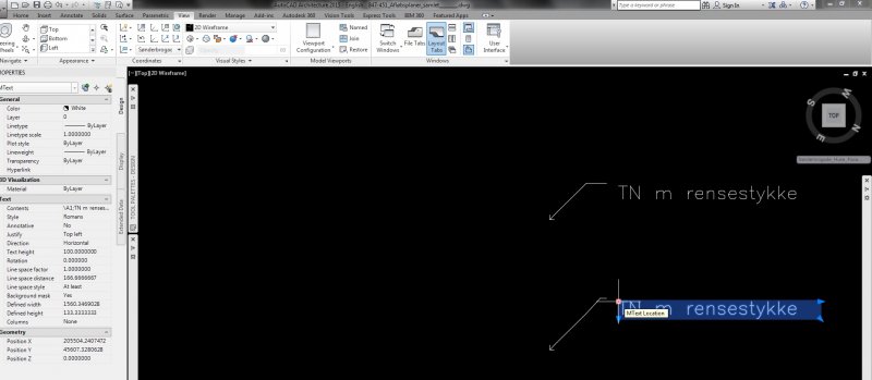
Hi Hope some of you can help solving a problem. When using QLEADER (le enter) in a drawing with custom UCS, the text are displaced away from the leader line. As you can see on attached screen dumps, it looks just fine, when in World UCS. When in a custom UCS, the text are displaced, and when I try to move the text, the leader follows (of course as normally intended). How can I make the text get to place itself normaly, when drawing in a custom UCS (2D) Please help :-)
-

text is mirroring when open on another machine
cadman9339 posted a topic in AutoCAD 2D Drafting, Object Properties & Interface
we are use autocad 08 and 07 full versions. my issue is when I use mtext or dtext for a call out or a note on my drawing, and I close the drawing with everything looking good, when we open it on our other machine the orientation is opposite so right is now left, so now some of the notes, not all of the text is not were it should be. If any one has any ideas please let me know. I'm not sure if this is do to a variable on the second machine or something else, we haven't change the text style and have used the same one for the past 12 years. -

Underlining a single line text
musasiojw posted a topic in AutoCAD 2D Drafting, Object Properties & Interface
How can i underline a single-line text in AutoCAD 2014? -
Hi to all, Please someone knows if its possible to create a field on a text form that could count a number of texts inside a drawing?... Eg.: I have the word "L1" 10 times in a drawing, it's possible to create a field that show me how many L1 I have in this drawing? Count of L1 = [10]; the item 10 it's automatic updates.
-

Number text based on content
cmaso posted a topic in AutoCAD 2D Drafting, Object Properties & Interface
Hi all, I'm looking to sequentially number all my text inserts but based on their content. For example, imagine I have 5 text boxes with the contents as "Text" and 5 with the contents "Number". I want the "Text" boxes to be numbered 1 - 5 and the "Number" boxes to be numbered 1 - 5. I'm aware I can use TCOUNT to auto-number them, but this would mean selecting each box individually based on it's contents. Does anyone know if there is a way of doing this, without using LISP? I have done a google search but I'm not coming up with much. Thanks in advance, Clare -

Dynamic Block that conforms to Text Length
3Darchitect posted a topic in AutoCAD 2D Drafting, Object Properties & Interface
Hi All, I am working on slowly creating some new standards for my office and am starting with some drawing tag blocks. What I need to know is if there is a way to have geometry stretch/move according to the length of a text attribute? For example, the tag name + some geometry that follows as a stylistic part of the tag. I made a block where the geometry in question is attached to a linear dimension attribute and I can use a grip to move it wherever I like. What I need, ideally, is a way where this follows the size/length of the text automatically. After searching the forum, there were one or two similar questions from several years ago, but no solid answers. Any help would be great. Thanks!