Search the Community
Showing results for tags 'custom'.
-
I have two lisp routines I'm using to enforce some CAD standards in our office. The first, STANDARD11x17, changes Dimensions, MLeaders, and MText to the appropriate styles. It prompts the user to "Include MText?" Yes or No. The second, NORMAL, changes all layer plot style names to "Normal". I've created toolbar buttons for these, using ^C^C (load "normal") normal When I type in the commands at the command line, everything works fine, but when I try to use the NORMAL button after running STANDARD11x17, I get the following error: Command: STANDARD11X17 Include MText?(load "normal") Can't reenter LISP. Invalid option keyword. Please help!
-
I want to make a lintype where line starts with a point and ends with the point and in between is continuous line. Space from points to line should be 1 or 0.5 units depending on the scale I want to plot my drawing in. Just in case there is somekind of confusion about how it should look like there is an image in the attachments. If anyone knows how to do it, pease help!

-
 Hi all, I'm trying to set up a button in my ribbon for a simple process I very regularly perform in AutoCAD 2010 LT. basically I want to: 1. Select everything in the model view (through an already active viewport) 2. Erase it all 3. Purge everything 4. Paste in whatever is in the clipboard memory (previously copied from a different drawing) and locate it at 0,0 coords. 5. Zoom Extents 6. Zoom out to 97% The macro below works perfectly fine as long as there were originally objects in model space to start with, but if I try this with a new file that has no model space objects (I only want one button) it stops at the 'select all' stage and refuses to continue. The error is the standard "Selecting objects...*error*" code and stops there. ^C^C_ai_selall;erase;all;^C^C_purge;a;*;n;^C^C_pasteclip;0.0;^C^C_z;e;^C^C_z;s;0.97x; Is there a way I can get this to work for both intances, when there are objects in model space AND when there are not? Michael
 -

Autocad lt 2013 - Line type Help
boxel0 posted a topic in AutoCAD 2D Drafting, Object Properties & Interface
I need a paticular linetype made, i have looked everywhere and have tried making my own but i am terrible. If anyone can do it and send me .lin file with it, i would be hugely grateful
-
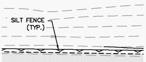
Sorry if this is a repost, although I doubt it. Can't hurt. As part of our Confuse-a-CAD-Monkey policy, we change our standards on every project. We had a custom linetype for silt fence years ago, which looked something like this: Unfortunately, every one of those pointy bits had to be drawn by hand, or at least copied, along an erratic border. I came up with a dynamic block (my first), but it was kinda clunky. Then we switched to a different linetype. Now we've switched back. I came up with a custom shape and put it in a complex linetype. If anyone wants it, here's the shape definition (in my.shp): *001,5,SILT 018,011,01F,018,0 Compile it as my.shx and put this in a .lin file. *SILTFENCE, silt fence -^--^--^--^- A,.25,[sILT,my.shx,s=.1],.25
-
Solution found.
-
Does everyone know how to insert xrefs with other ucs than world. The host drawing ucs must be in world. The different x-refs are made with different ucs according to local coordinates. In the host drawing, the xrefs must be placed correctly according to global coordinate (world). (The xrefs are all surveys of different spaces all with marked fixpoints according to the physical global coordinates.) please help...
-
Hello everyone, this is my firs post, so greetings. I have been given the task from my director to produce a concept for the following: when a member of staff opens AutoCAD (2011) there is an interface that pops up that has two buttons. The first being A3 and A4. The idea is that when each of these is clicked, a new template is opened ready for them to use, that has out title block and layers etc all set up. Does anyone know where I should start with reference to custom interfaces on AutoCAD startup? Thank you in advance for your help!
-

Adding SHIFT key when editing Command Aliases
Leave Me Here posted a topic in The CUI, Hatches, Linetypes, Scripts & Macros
I'm running Autocad 2011 on MAC (dont ask why, its just needs to be done..) and now I'm struggling getting all my old keyboard shortcuts from PC setup up again. Does anyone know how to include the SHIFT key when editing/customizing the command aliases?? ie, i want SHIFT+V to = MOVE So in the Command Alias text file, Im guessing it should look something like this? SHIFT+V, *MOVE But that doesnt work. I really really want to stick with this format, and not need to include other control keys, ie CTRL+SHIFT. Any info or help would be great! Cheers, Matt -
Hello Everyone, I am new here and have a new question for you guys. Forgive me if this has already been asked. We have some old timers at the company who have extensive tool palettes with all kinds of custom goodies that they want to distribute to everyone else in the company, or atleast make them available on the network drive. I have already found out how to export and import profiles to make my station's setup look like theirs. I have also exported custom tool palettes but the blocks that are the meat of the palettes aren't there. I get the error "Source drawing "C:\BLOCKS\P&ID\AB001.DWG" for block "AB001" not found." How do I get the source drawings for the button to be active? Any help given about this will be greatly appreciated. I am sure its just a matter of copy and pasting the source files from "a to b" but I need the locations and other details. Thanks much, Ridley ....
-
I've posted an earlier version of this in the past, but decided to update the code and provide a proper write-up. Designed as a bit of fun, the program will allow you to create your own custom Tip of the Day messages, which will be randomly selected and displayed once each day. Whether it's used to constructively provide help for AutoCAD users, or merely provide a funny message for each day - I leave it up to you Have fun with it! Lee Code is available here - if you have any questions about how to set it up, let me know.
-
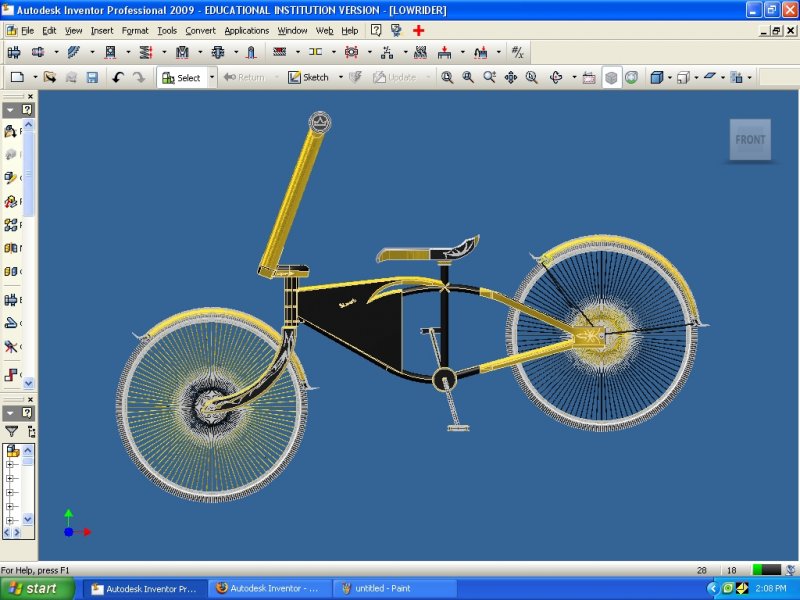
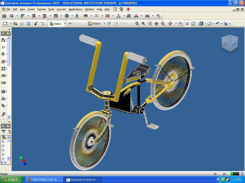
I'm building a custom lowrider bike which ill later post and i already have all of it done but i need to build a chain for it and i don't know how. and i also need help with making twisted bars for the handle bars. if you can help that would be awesome!
-

I need help tweaking this swale linetype
JAM posted a topic in The CUI, Hatches, Linetypes, Scripts & Macros
Swales have always been finicky to draw with the proper annotation and it seems to be a common inquiry of forum users to find a code string that creates one automatically. I got sick of waiting and searching so I developed a code string that draws/repeats the squiggly line and triangle arrow annotation for me to make things faster and easier. It works (kind of) but it draws a continuous line over the swale symbols almost like a strike-through in MS Word (see attached image). I wouldn't mind it so much if it was a standard centreline symbol but my preference is for the "line" type to just be the repeating symbol and not have a line at all. Here is the code I've come up with (it is scaled to draw properly in inches--for metric scale the ltscale to 0.03937): *SWALE,Swale --> --> --> --> A,0,10,[sWALESYMBOL,swalesymbol.shx,x=1,s=1],65 I've saved it into my acad.lin file along with my swalesymbol.shx file which is just the squiggle and the arrowhead. When I draw a line or polyline using the linetype though I still get the solid line. Perhaps someone can post a reply that takes my code and tweaks it?
-

Custom DASHED lines with text
freek posted a topic in AutoCAD 2D Drafting, Object Properties & Interface
Hello community, it's been a few weeks with no activity whatsoever on the forum, but I'm back for a with a good one I've been customizing acad.lin like a maniac for the last couple of days and there's a recurring problem that I can't resolve by myself. I have this line... *EX-DASH,[G] Existing - - EX - - - - EX - - - - EX - - A,.125,-.0625,0.127,-.254,["EX",STANDARD,S=.127,U=0,X=-.127,Y=-.0635],-.2,.125,-.0625,.125,-.0625 The result is similar to... - - EX - - - - EX - - - - EX - - - - EX - - - - EX - - - - EX - - Let's say that the pattern of the line ("- - EX - -", because that's the part that's being repeated) takes 50 units to display at a given scale. I draw a PLINE and one section of the line is like 75 units long. If the line I'm drawing can't contain the pattern of my custom line, it won't display correctly. Given these numbers, the pattern would only display right once (75 / 50 = 1.5). *And the crowd goes DUUUUH!* I get that and it's ok. HOWEVER, one thing I don't get is why autocad displays the pattern once and then fill the rest with a continuous line. It's okay for all my continuous custom lines with text because it keeps the same base line and it feels transparent (and it's also the reason I never realized it was reacting this way until I started working with dashed lines). Example: I want to display "- - EX - - - - EX - -" but would only have space for "- - EX - - - - E". Acad will display "- - EX - -" once + continuous line for the remaining space. I know that if there's no space to fit a second "EX" it can't be displayed, and that's allright, but how come it doesn't fill the rest of my line with dashes instead of a continuous line? With PLINEs, every time I turn a corner, I get this continuous line segment on each corner before it starts displaying the dashes (because I can't always draw lines that fits perfectly the pattern). Any idea on how to force it to display dashes when there's not enough space to repeat the pattern one last time? -

Custom Hatch Patterns Containing Text
gman1979 posted a topic in The CUI, Hatches, Linetypes, Scripts & Macros
Hi, I'm familiar with creating hatch patterns using notepad, I have been scouring the web for any examples that meet what I’m looking to do: I'm looking to create a customer hatch pattern where text is defined within the pattern in the same way text is defined within a custom line-type. So far, the only examples I have found show the text being drawn line by line. I don’t know if it is possible to do what I’m looking to do, although I’d be surprised if it can’t be done in some way. Any help would be appreciated even if it's to tell me it can’t be done - as it would save me a lot of time going through the forums & AutoCAD help file. Thanks in advance Gman Running OS: XP, AutoCAD 2008