Search the Community
Showing results for tags 'orientation'.
Found 7 results
-
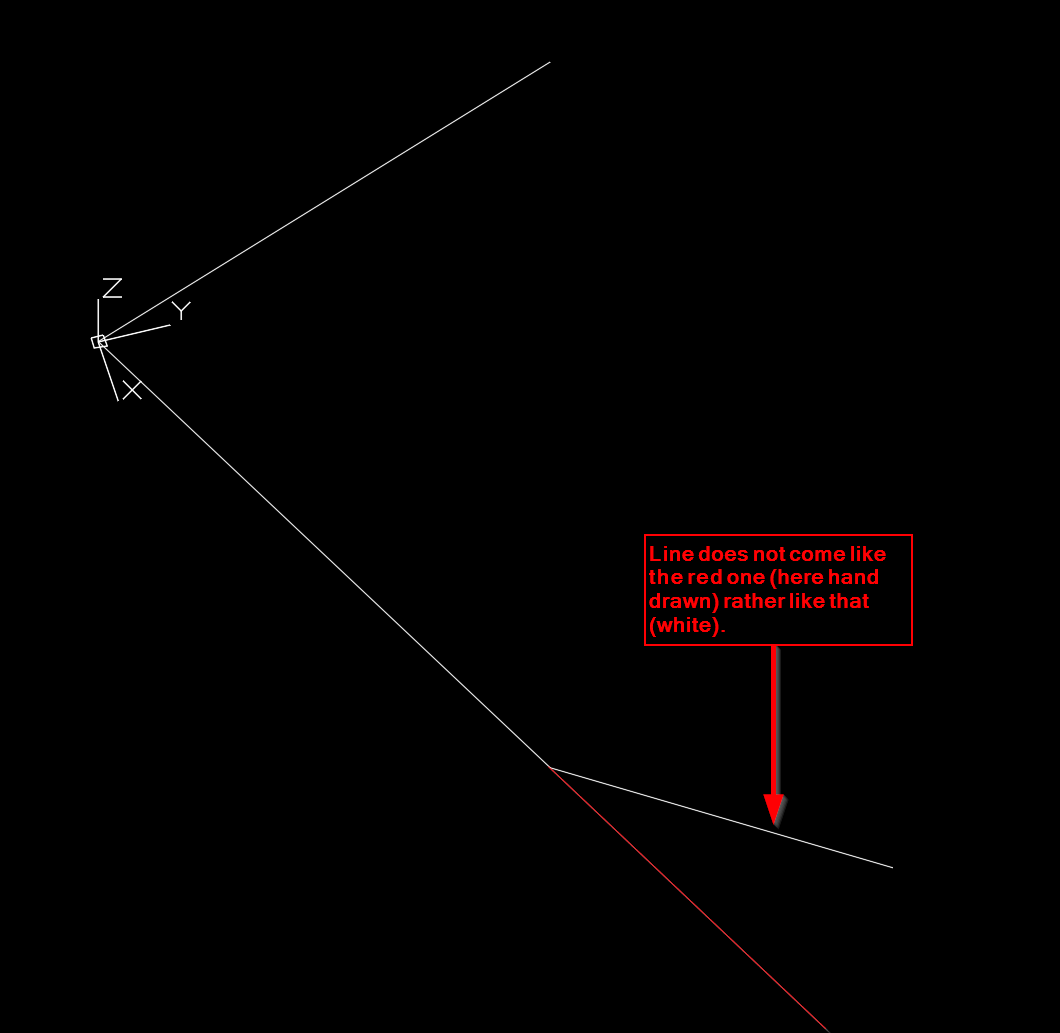
In continuation of this thread I would like to continue this interesting story about UCSs and transformed entities. So far I have understood ( I am thankful to the community here) that An OCS is an coordinate system that most of the Autocad entities use instead of any other CS An OCS share the same origin with the WCS, however its x,y,z may be other than the one of the WCS However, it seems that something still eludes me and I cannot fully grasp it. I made a very simple model with a line drawn in WCS from 0,0,0 to 1,2,3. I would like to insert the same model on this one, that is having this line sitting on the end point (1,2,3) of the other as an extension. That means the lines need to be collinear. Let's assume I mirror3d this line on the xy plane, so the extrusion vector now becomes 0.0 0.0 -1.0. Using the following snippet the line comes on the correct placement but the orientation is wrong. What am I missing? ; clicking the mirrored entity from 0,0,0 to 1,2,-3 (setq pt (cdr (assoc 11 (setq ent (entget (car (entsel))))))) (setq v (cdr (assoc 210 ent))) ; inserting the drawing (entmakex (list (cons 0 "INSERT") (cons 2 "Dwg") (cons 8 "0") (cons 10 (trans (trans pt 0 1) 1 v)) (cons 70 0) (cons 66 1) (cons 50 0) (cons 210 v) ) ) Any suggestions appreciated.

-

Dynamic block attriboute text readable direction
gegenytibor posted a topic in AutoCAD 2D Drafting, Object Properties & Interface
Hello, I created a dynamic block with arrows and an attriboute text. I had to use multiline text because I need background. When I rotate the block the text is not in the good direction on the left side (the other three way is ok). Is it a way to orient to the readable way the attriboute text somehow in the rotated block? Thanks for the answers! TB arrow.dwg
-

How do I control the orientation of a dynamic block?
Vagulus posted a topic in AutoCAD Drawing Management & Output
I have been working with dynamic blocks - windows and doors - and I have trouble getting them into the right orientation and keeping them there. If this video works it'll give you some idea. My major problem is that when I try to move the hinge of the door to the door jamb the block orients itself any way it wants to go. I have a real job tricking it into going into the right place the right way around. Would someone please lay out the steps so that the process works, and works consistently. -
 Does anyone know how to make txt orientation match layout without also having annotative scales. I need the txt to be a fixed size according to other drawing objects in different viewports -with different scales - and with different orientation. Sorry for writing messy. Hope someone can help:cry:
 -

Custom linetype with text display problem
freek posted a topic in AutoCAD 2D Drafting, Object Properties & Interface
Hello community! My love for this forum keeps growing, so here I am again. Today's issue... I made a custom line type called EX (for existing pipes) which looks a little bit like this: - - - EX - - - EX - - - EX - - - Line works great when I draw from left to right. However, when I draw a line from RIGHT to LEFT, the text displays upside down a little bit like this: - - - X3 - - - X3 - - - X3 - - - ("3" representing the mirror image of "E") Same applies when drawing from bottom to top, or top to bottom. I totally understand the behavior here, and TBH I think it's OK it behaves that way. But some people at work blablabla... (you know the drill). Let's say I'm drawing existing water pipes going in all directions with a polyline. Is there a way to make the text display upward no matter what direction the pline is going? Thanks -
My company recently hired out some AutoCAD work. The task they completed was to load our drawings from pre-CAD days (1970s and 80s) into AutoCAD and update them with new piping and notes. Somehow, when they did this, the drawings in model space ended up sideways, but they are right-side-up in paper space. This is making it very difficult to work with the drawing in model space. A simple rotation of the entire model space drawing does not solve the problem because the xref files are correctly oriented, and they do not rotate with the added notes, etc. Also, it does not work to rotate just the notes and realign the leaders because then the drawing ends up sideways in paper space. There must be some way to fix this, I just can't seem to figure out how. Help? Thanks!
-
I'm using Civil 3D for the first time at a new job. We have a deadline this week so I'm super grateful for any (urgent) help you can provide me. I went through all the wizard steps to create my viewport sheet template, then the view frames in my drawing, then the sheets from my drawing. My questions/issues: First, when I produce the sheets, the drawings show up with north to the right, but I want north to be to the left, just as it is in my model space. North is normally up, but we are printing a very long site in landscape layout (not profile) and have set North-South to run Left-Right. Second, when I print to pdf, only my alignment shows up. Nothing else prints. Just a single line on the page, nothing else. Third, how do I edit a View Frame Group? It seems I need to make an entirely new group every time I make a new viewport template. But I just want to keep the View Frame Group I have and edit the template it uses. Fourth, out of curiosity, what is the (CP) for after [Next Counter]? Thanks so much in advance, Forum community!