Search the Community
Showing results for tags 'c3d'.
Found 15 results
-
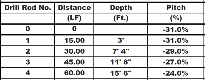
Hey guys, I have a HDD bore I'm working on getting a rough sketch into autocad. I have over 60+ rods on some of the drills. I am wondering if there is anything that asks for typical rod length and then I can import either a .txt or excel file to get rod angles from? The lisp I am looking for would, in this case, put polylines 15 feet long, back to back, at the respective pitches (-31%, -31%, -29%) which I converted into angles in degrees. Let me know how I can go about this or if anyone wants more information. Thank you.

-

Insert point below line X distance at Y station
Shablab posted a topic in AutoLISP, Visual LISP & DCL
I have contours of a site as well as an alignment with stationing. Along the alignment, points were taken and show how deep we need to go in respect to existing grade. What is the best way to show these points at the certain depth needed (X) taken at the station along the alignment (Y). I was going to create a separate feature line along top of the alignment to follow stationing and edit the depth/points in the panorama to then project the feature line to the profile. However, this seems tedious for the amount of profiles I have. -
Electric Transmission poles
Shablab posted a topic in AutoCAD 2D Drafting, Object Properties & Interface
Are there any resources I can take a look at to find all different types of electric transmission poles in autocad. -
I keep getting this on my drawings. I click update reference name and the next time it synchronizes I get the same message again. How do I make it go away?
-
I am having a hard time converting a .las file to create a surface in C3D & I was wondering if anyone had familiarity with this. I brought the .las file into ArcGIS and created a Raster then extracted contours from the raster but this did not work out the way I hoped. I see that C3D is able to open .rcp & .rcs files. I was wondering if this would be the route I need to take and how do I convert into either of those formats? One work around I've used is using Autodesk Recap to convert the files but my issues then stem from the surface thinking the trees are ground points.
-

user interface Locking the location of the "Text Formatting" box when editing Text
Incognito Cube posted a topic in AutoCAD 2D Drafting, Object Properties & Interface
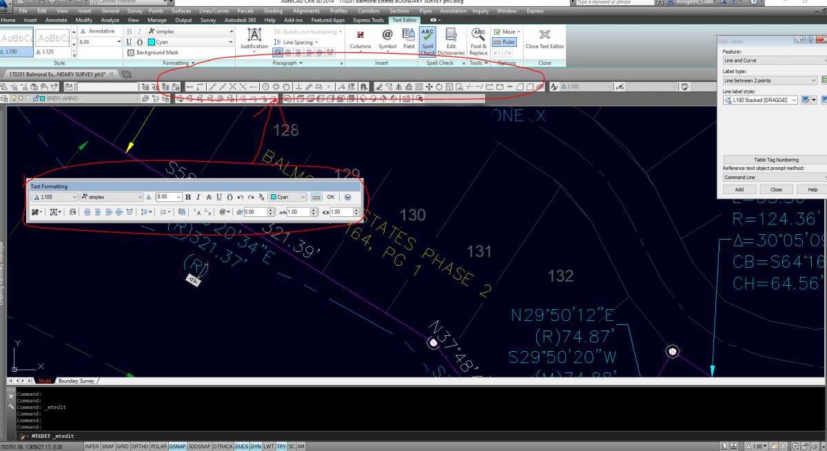
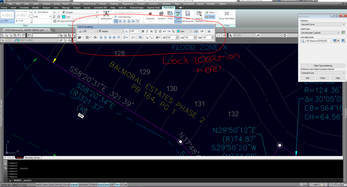
Hey everyone! It's been a minute. Quick one here... Is there any way to lock the location of the Text Formatting box that pops up while editing text in C3D 2014? I'd prefer it to pop up over my Ribbon, rather than in the actual Drawing Window. See below for clarification. I thought I saw this ability in the CUI one time when I was helping a co-worker, and even thought to myself "Oh, hey! That would be very useful for my text editor!" But of course, I was pulled off to work on something before I got back to my machine to set it up, inevitably forgetting my personal task completely.
-
Hi, I am looking for some help with outputting point elevations in a format similar to that of nautical charts (see attached). My survey software can export a number of formats including DWG and DXF. I have been using autoCAD for basic drafting in the past and feel this is a little out of my league. i will have a number of projects coming up that will require this and any help now would be greatly appreciated. i have uploaded a sample of the data of what i normally export from my survey software (Magnet Office). Many Thanks Peter SurveyData.dwg
-

Creating custom coordinate system (with datum parameters TOWGS)
Kevin Malone posted a topic in Civil 3D & LDD
I'm tying to create custom Coordinate System in C3D 2012 with datum parameters (Dx, Dy, Dz, Rx, Ry, Rz and scale), but during the creation process (thru MAPCSCREATE function) I don't get anywhere to input this values. As you can see on screenshot, TOWGS parameters are all "0". Only way to form some kind of datum with parameters is creating Geodetic Transformation, but I can't link/import that in my CS definition I would appreciate any help -
I am receiving error message "surfaces do not overlap" when i try to get volume between two surfaces.. i have two surfaces: 1. Made up of Survey points 2. Polyline which i put an elevation to make it 3d poly and then convert it into block before making it a surface. What could have I done wrong? Help me please
-

Vertical Surface Comparsion?!? Is it even possible? You tell me..
Mallen1987 posted a topic in AutoCAD General
So I have two 3D scans of a retaining wall (one from 2013 and another from 2014) and I need to compare the two and see if it has moved. I am wondering if anyone in the world knows how to do so. Since the surfaces are vertical, and not horizontal, this has become a real 'head-scratcher' for me. I've tried to use the 'X' values as elevations, but since the retaining wall is not due east-west in the 'real-world' it isn't along the 'X' and 'Y' in AutoCAD, therefore when I tried to compare the surfaces, I get a gradual increased elevation difference from South-North due to the rotation from North (in the real-world) and the coordinates produced... SOMEONE PLEASE HELP, I CAN PAY! -

Flat Install of C3D 2009 not working - Failed to Copy SetupRes
wwentllc posted a topic in Hardware & Operating Systems
I had Vista crash (go figure) and had to do a restore. I am trying to reinstall AutoCAD civil 3D 2009 (discs are bad and Autodesk does not have any copies as the only support the last three years) from a backup from an external harddrive. I click on the setup.exe file and it begins to initialize and then pops with an error " The copy function cannot be used. Failed to copy the following file: SetupRes to C:\Users\\AppData\Local\Temp\… I can see that files have been copied to the folder but not sure why the error message. Can anyone help? -
Using this tool, I was trying import the Parcels in C3D into the SDF but every time I do it I only get Parcel Name, area and perimeter. I need the parcel number too but it is not exported. Is there an ini configuration somewhere to turn on export for these attributes? Using C3D 2013 32 and 64 bit versions.
-
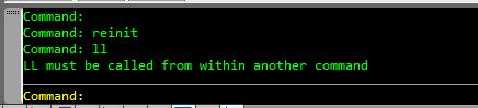
Hello everyone! I have customized my .pgp file (in C3D) so LENGTHEN is represented by LL rather than LEN. The issue is, that if I use LL, I get an error message on the command line that reads: "LL must be called from within another command" LL doesn't represent anything else in C3D and LL works great in ACAD with Land Desktop. Anyone have any ideas? P.S. I guess there's a possibility that LL is already "pointing" to something else but if that's the case, I don't know what that something else would be?
-
Hi all, So maybe I'm just too old or stubborn, but after upgrading to C3D and AutoCAD 2010, I'm not pleased with the new workspace setup. Specifically the ribbons drive me crazy. I liked the old 2008 version with toolbars. (I feel like the ribbons are too bulky and it's not as easy to get to certain commands, but I digress). With AutoCAD, changing the workspace to the old 2008 style is easy: workspace --> setCurrentas --> "AutoCad Classic". However, it doesn't appear to be that simple in C3D. Such a workspace setting doesn't seem to be available. My question is, does that setting exist, or if not, is there some way I can get my trusty old toolbars back? Thanks!
-
Currently, I am trying to make a TIN from predefined contours of both the existing ground as well as the proposed ground so that I can perform volume computations. I am able to create the surface but the problem I am having is getting the units of the contours and the units of the surface to agree. For example, I was given a file from the surveyors that has contour lines with elevations ranging from 175 to 185 feet. When I make a TIN surface from the contours, it converts the elevations of the contours into feet, making my surface elevations range from approx. 14.5 to 15.5 feet and thus throwing off the volume calculations but a factor of 12^3. Can anyone help me get this straigtened out? Is there a setting that I am missing or something to cause this to happen?