Search the Community
Showing results for tags 'hvac'.
Found 10 results
-
Version 1.0.0
4,843 downloads
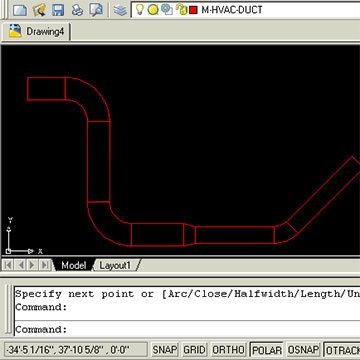
This is a program made by ASMI and modified by Ronso in this thread. This is a genius free LISP Program and can be used in many trades, but has most usefulness in the HVAC, Mechanical, and Piping industries for drawing 2D CAD designs. It allows you to create Duct, Pipe, and Segmented Duct or Piping with automatic elbow or fittings to accurate dimensions via some initial input at the command prompt. The programme in action Function Syntax: DUCT For instructions on how to run the program see here. -
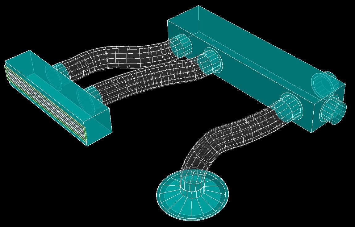
Hi guys, I'm new to this forum and new to programming with lisp - please be kind.... The code I am writing will draw a 3dPolyline from a specific point to another point (usually with a lower z coordinate), the polyline will then be converted to a spline, a circle will be drawn at the start of the 3dPolyline and extruded along the spline to form a "curved tube". The intention is to use this as a flexible duct from a "spigot" on an A/C duct to a ceiling diffuser. The 3dPoly has to be perpendicular to the start point and end point for obvious reasons - see intentional misalignment picture. Below a portion of the unfinished code to select the start point, select the endpoint, then it must start drawing the 3dpoly from the start point, get a variable number of user input points (in order to define the initial direction and plane) and general path of the flexible duct. The end point of the 3dpoly is already defined with the initial selection of the "Endpoint on Diffuser" although the 2nd last point has to be mathematically determined considering the plane must be perpendicular to the end point. So - after selecting say 3 or 4 user defined points along the path, I want to be able to press enter, and the code must then calculate the 2nd last point and continue drawing the 3dpoly from the last picked point, to the calculated 2nd last point and then to the endpoint. Generally one has to be mindful that the curve of the tube cannot have a "sharp bend" - smooth curves are ideal for the airflow. The diameter of the tube will also change depending on the specific size requirements. Attached a small drawing and picture to show the intent. The crux of my problem: I cannot figure out how to start the 3dpoly command, make it pick the start of the line, then hand over to the user to continue picking 4 or 5 points, press enter, and then continue drawing the 3dpoly with calculated numbers? Would really appreciate some guidance. Maybe use of cmdactive? I really do not know enough to figure this one out. (defun C:Flex250 () (command "_.layer" "_thaw" "HVAC Flex" "_make" "HVAC Flex" "") (setq Prev_OM (getvar "OSMODE")) (setvar "OSMODE" 8) (setq StartPoint (getpoint "\nEnter Start Point on Duct Spigot : ")) (setq EndPoint (getpoint "\nEnter End Point on Diffuser : ")) (setq Z0 (caddr EndPoint)) (setq Z1 (+ (caddr EndPoint) 50)) (setq Z2 (+ (caddr EndPoint) 150)) (setq pt0 EndPoint) (setq pt1 (list (car EndPoint) (cadr EndPoint) Z1)) (setq pt2 (list (car EndPoint) (cadr EndPoint) Z2)) (SetVar "Elevation" (princ (caddr StartPoint))) (command ".3DPoly" (princ Startpoint) (getpoint "\nNext point : ") pt2 pt1 pt0) ) Then a last question - is there a way to ensure the spline's start and finish points are 100% perpendicular to the planes they connect to? Thank you in advance for your input. Test.dwg

-
Hi friends, this is my first post here . I am relatively new to Autocad MEP . I recently got a job as Mechanical Engineer in an HVAC design and installation firm in a junior level, and I need to practice before joining. I tried learning the software by my own through youtube and several of my doubts have cleared through google. But some things cannot be solved by google search and hence I have arrived here. I have taken the autocad 2d plan of my own house from my Dad , and started practicing drawing and sizing the ducts . I have attached the dwg file here : Final file - https://www.dropbox.com/s/84lqro3b701m6lk/mukatra.dwg?dl=0 Used for Xref ground floor plan- https://www.dropbox.com/s/x8e241aat9pukye/Mukkatra%20mep%20ground.dwg?dl=0 Used for Xref first floor plan- https://www.dropbox.com/s/rqfe5xoyxwhe8r2/Mukkatra%20mep%20first.dwg?dl=0 These are my doubts: 1) I wish to know my duct modelling method is correct or not . I roughly estimated the flowrate required for each room , divided it by the number of diffusers that I wish to place , got the flow rate for each diffuser and assigned it to each diffuser after placing them in a room.I followed this step for all rooms . Then I started the duct drawing . I chose 2 line duct method and started from the major trunk , selected all diffusers of the same floor , got total flow rate and and duct size was obtained (medium pressure lane - velocity around 5m/s). Is this the right method ? 2) I roughly placed the diffusers just to practice drafting. In the professional way, how to place them at particular distance from walls? I know the array function only . May be this question is dump ,but trust me I am new to Autocad thts why. 3) I have assigned different layers for each floor , ie blue for ground floor ducts and red for 1st floor ducts. This was done hoping that I can hide them when needed to take print out . Sorry for my stupid idea , plz tell me which is the real method to take prints in 2d for each floor separately . 4) While taking the 2d view after hiding all other floors , some of my ducts and connectors are partially visible . Its like if some portion got erased with an eraser partially. How to fix this ? 5) This one might be the stupidest of all. Does layer color come in printout ? If I choose light green , Its barely visible ? like that? or all comes in black ? 6) In the schedule table , which I plan to create consisting of duct length and duct size , I wish to give them a series-name or tag . And I need these tags to appear in the drawing on each ducts or very near it. I have no idea how to create tags for ducts. I can only see tags for air terminals and some other stuffs. I need tags for all the things in my drawing. My wish is to make the drawing easy to understand. A simple numbering over the ducts or equipment will be enough . I will sort and group them in scheduling table. 7) Some say , autocad 2d is used for hvac drafting in most companies . Why dont they use Autocad MEP ? The standard library of autocad mep doesnt match with SMACNA standards? Or is it the difficulty to create custom equipment in the library ? Or is it the fact that even if we make in 3d , the printout will be always in 2d ? All the features in autocad 2d can be done in 3d anyway right? Is it possible to change the diameter of an air terminal like diffuser in our list of diffusers ? I know they have different diameters or l x b , but I wish to knw the method for modifying it. When I googled , I saw a big tough method to import a library list or something like this and copy the default list etc etc . I just need to create a new diffuser with a custom diameter with the existing design, possible ? 9) Usually , is schedule table printed along with the plan ? or is it just exported to excel and taken print ? Can the method of scheduling used to create bill of materials in excel ? Is this feature available in autocad 2d? This is a great advantage over autocad 2d? 10) The formula used in duct sizer is the same as the one in autocad mep right? duct sizer uses the simple formula - q= vA and darcy weibash equation right? the same with autocad right? 11) After I drafted , I didnt right click on my duct and choose - 'calculate duct sizes'. Since I had already sized the duct accordingly when drafting by the method described in point -1 . In the analysis tab - view by friction option was there. I was curious and tried it . But the all ducts were green in color despite I saw the duct friction loss higher than 0.7pa/m . Green was supposed to be Out of these questions , I wish to know about the right method to take print (mentioned in doubt 3) for duct plan in each floor separately and doubt 6 is very urgent and consumed my entire day. Please understand that I have been learning this for a week now by my own and many of my questions might be silly for you. The tutorials available in youtube is very less compared to some other software such as solidworks , catia , ansys or abaqus etc . So , each doubt takes a lot of time searching !! Please help guyz , Ill be really grateful . When I become expert in autocad , i will also be helping the new people , but I should master it first
-
Hi all, Could you please advise me an easy method for having a separate file for a particular system. e.g.: I had a Revit mechanical file contains hvac piping, ducting and steam piping for boilers, now I need only the steam system in a separate file. Could you please assist..? rgds, john
-
Hey Guys, I have the following problem. I'm working on HVAC project and after I have almost finished the whole project the managers company sent me new template layers file ,that I should follow. So now my "17_COOL_MEPA_SUP" layer and all of his futures (including color,line thicknes and so on) need to be changed to "10_C_HVAC_S" with other futures (different color,different thicknes). I know that I can rename group of layers by using script file ,but can I totally replace group of layers with another group? P.S. I have 130 drawings ,so the manual method is not an option. HEEEEELLLLPPPPP!!!!
-

mep best workflow practises for hvac design detailing for fabrication
wanabdrummer posted a topic in MEP
Hello everyone, my work has asked me to start using autocad mep to detail drawings since I have a little autocad experiance over the years. computer is up and running,acad mep installed,trimble design link installed,ready to go. now what? What file format do i need to get started /dwg ? i assume. I just need a push start and a little help to get a project started. any suggestions would be appreciated. I will be taking a few courses but nothing scheduled for a month or so. -
Hello, I am new to AutoLISP and I have been trying to find/create a code that will simplify drawing HVAC ductwork. I have found an existing code from an autodesk discussion group: http://forums.autodesk.com/t5/Visual-LISP-AutoLISP-and-General/Doubleline-Duct-lisp-routine/td-p/3198454 (The last posting: DUCTNEW.lsp) This code is meant to do exactly what I am trying to accomplish, except that when it prompts "continue, split, double-split, transition" the only command that works properly is . Any tips or help would be greatly appreciated
-

Measuring ventilation ducts area
Puzon posted a topic in AutoCAD 2D Drafting, Object Properties & Interface
Hello As a hvac calculation engineer i often need to measure quickly pipes length and ventilation ducts area. Measuring pipes lenght is quite easy with qselect + tlen.lsp, but, so far, i've no idea how to measure ducts area quickly. I'd like to add that ducts surface seen in 2D would satisfy me and i only talk about 2D drawings. Do You have any idea how to do this measure? Maybe there are lisp routines that could help? -
Okay so i was doing my HVAC/sheet metal drafting all smoothly, doing all the hvac and vents. until, suddenly, and with out warning, an instruction from the booklet was so confusing, i momentary cannot find out what to do. this is my questions in which im stuck. 3. The eastern portion of the split is 10″ wide and connects almost immediately to a 10 × 14 transition piece. The 14″ × 6″ duct continues south to a point near the sink in Bathroom #2 where it splits into two portions. 4. The west portion forms a 4″ × 4″ duct that bends west and connects immediately to the wall outlet scheduled as S-B2. This outlet is located in the toe clearance between the washbasins in Bathroom #2. The 4″ × 4″ duct exits from the west side of the outlet and continues west to end in Bathroom #1. The very end of the duct connects to the 4″ × 12″ wall outlet scheduled as S-B1. Like the other bathroom’s outlet, this outlet in Bathroom #1 is positioned in the toe clearance between the washbasins. so far i have no understanding of what it means. what are toe clearances? this my work so far plate 1.dwg so can u give me a brief explanation. anyone that helps gets a virtual cookie.


.jpg.7ebd8746138284fcdebcc66a1bacb533.jpg)


