Search the Community
Showing results for tags 'dimension'.
-

How to control lineweight i dimension?
jrn posted a topic in AutoCAD 2D Drafting, Object Properties & Interface
When drawing in .stb-file (with layer dependent plot style, plotting in monochrome) and when Dimension Text Style is set to Romans (must not be changed), then how to change line weight of Lines and Text separately? Please help. Thanks. -

dimension text question
toberino posted a topic in AutoCAD 2D Drafting, Object Properties & Interface
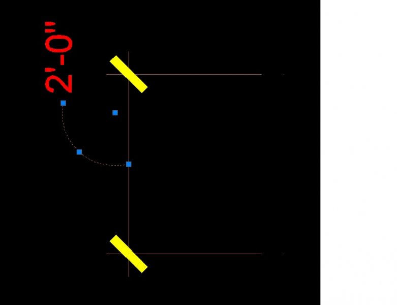
Does anyone know of a way to automatically insert the arc like the picture? Is there a setting somewhere that will do this? Right now when we have a location that cannot accomodate the text we are drawing an arc and grip moving the dim text to the new location. I am trying to find a more automated way to handle these types of situations. Thanks
-
Ever wanted a dimension for the grade of a slope. (when drawing in 2d/plan) well i have, so i created this lisp to save time in manual calculating and creating some text. ; Grade ; ; by Robert Condon ; 13/9/12 ; ; ; To use: Select two points from left to ; right and it will give you the ; grade between the points ; ; ; (defun c:grd () (setq p1 (getpoint "\n1st point of Grade:")) (setq p1X (car p1)) (setq p1Y (cadr p1)) (setq p2 (getpoint "\n2nd point of Grade:")) (setq p2X (car p2)) (setq p2Y (cadr p2)) (setq rise (- p2Y p1Y)) (setq run (- p2X p1X)) (setq textposY (float (if(> (+ p1Y p2Y) 0) (/ (+ p1Y p2Y) 2 ) (setq textdisp 0) ))) (setq textposX (float(/ (+ p1X p2X) 2 ))) (setq textpos (list textposX textposY 0.0)) (setq trot (angle p1 p2)) (if (> rise 0) (progn (setq rise1a (/ run rise) ) (setq rise1 (rtos(/ run rise) ) ) ) ) (if (< rise 0) (progn (setq rise1a (/ run rise) ) (setq rise1 (rtos(/ run rise) ) ) ) ) (if (> run 0) (setq grade (rtos(* 100 (/ rise run)) ) ) ) (if (< run 0) (setq grade (rtos(* 100 (/ rise run)) ) ) ) (if (>= 9.999 rise1a) (setq textdisp (strcat "[url="file://\\pxsa1.4286"]\\pxsa1.4286[/url];" rise1 ":1")) (setq textdisp (strcat "[url="file://\\pxsa1.4286"]\\pxsa1.4286[/url];" grade "%")) ) (if (progn (> 1 rise1a)(< 0 rise1a) ) (setq textdisp (strcat "[url="file://\\pxsa1.4286"]\\pxsa1.4286[/url];" "1:" (rtos(* rise1a 100) ) )) ) (if (progn (< -1 rise1a)(> 0 rise1a) ) (setq textdisp (strcat "[url="file://\\pxsa1.4286"]\\pxsa1.4286[/url];" "1:" (rtos(* rise1a 100) ) )) ) (if (= rise 0) (progn (setq textdisp "")(princ "\nGrade is flat")) ) (if (= run 0) (progn (setq textdisp "")(princ "\nGrade is vertical") ) ) ;(setq text size (getint "Text size: ")) (entmake (list '(0 . "MTEXT") '(100 . "AcDbEntity") '(67 . 0) '(410 . "Model") '(100 . "AcDbMText") (cons 10 textpos) '(40 . 0.5) '(41 . 0) '(71 . '(72 . 5) (cons 1 textdisp) '(7 . "ISO3098B") '(210 0.0 0.0 1.0) '(11 1.0 0.0 0.0) '(42 . 0.833333) '(43 . 4.66667) (cons 50 trot) '(73 . '(44 . 1.0))) (princ) )
-
I have read some posts which encourage to draw the drawing in MS without dimensioning and do it in PS. This will solve the scaling of dimension properties like text height and arrow size. One dimension style could be used for all VPs in PS with different scales to maintain the uniformity. While drawing in MS, I need to know the dimension and that is why I am forced to put dimension in MS to ease the drawing process and avoid shifting back and force between MS & PS. Those members who still support dimensioning in PS, how solves this issue? I would like to hear members experiences and comments.
-

inputting imperial units
mgervais posted a topic in AutoCAD 2D Drafting, Object Properties & Interface
Im having trouble inputting imperial units for my line lengths. It works fine when i type 4-3/4 it gives me a line that is 4 and 3/4 of an inch long. Can i only input values in inches or is it possible to input something say 4' 4-3/4 ?? Thanks -
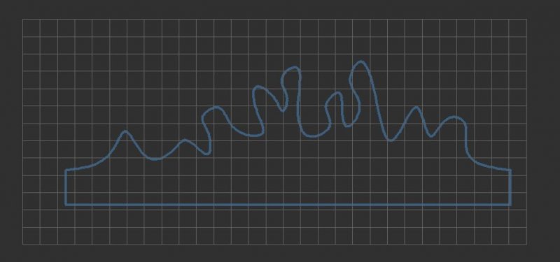
 I have a really curvy sculpture. How do I draw the dimensions of the elevation for it? I have attached a picture of my drawing. I was told to do gidelines and show the dimension of them. However I find it not very accurate for the contractors to read. Any advice would be appreciated. Thanks in advance:D
-

Flip dimension measurement?
D1-Xen posted a topic in AutoCAD 2D Drafting, Object Properties & Interface
How do we flip the dimension numbers from one side of the line to another? My dimension always appears on the left hand side for a vertical line and on the top for horizontal line... Can I make them appear on the bottom or right side? How do I do it? Command: DIMLINEAR -
When doing batting insulation is there anyway to define its dimensions? For example, i want the width to be 150mm from center, making it 300mm thick I know i can adjust the size view of it with the annotation scale, but i would like to be able to define and exact dimension instead, not the scale. This would help a lot when drawing wall detail. Thanks guys!
-
Hello everyone, I have a viewport with two loading bays about 50m apart. I want to use a higher scale to make it more visible but wont fit on the page. I have seen this before but unsure as to how to do it, I want to put a breakline in the viewport so the scale can be bigger but have the same dimension distance. Any suggestions Thanks Sam
-

Dimension units change after saving
davidad posted a topic in AutoCAD 2D Drafting, Object Properties & Interface
I'm having an issue with dimensions changing from when I save the drawing to when I reopen it. I'm using AutoCAD Mechanical 2009, exclusively in 2D. I save drawings in AutoCAD 2000/LT 2000 Drawing format to maintain backwards compatibility with our legacy documents which are still in regular use. The exact process is: 1. Create dimension in existing drawing. 2. Set units of dimension. Typically this is fractional. 3. Save and close drawing. 4. Reopen drawing, and all of the dimensions units are set to decimal to the fourth decimal point. If I interact with the dimension in any way, it will return to its set unit. For example, if I double click on it to bring up the Power Dimensioning window and just click Okay without altering anything, it will change back to its set unit. Likewise, if I move the dimension itself it will return to its set unit as well. So far my solution has been to simply select the entire drawing at once, then move it X units one way, then X units back. The move back and forth will return all the dimensions to their set units. Obviously this is not ideal, especially when sending drawings to co-workers who are unaware of the issue or even using different versions of AutoCAD. Thanks for any help. -

AutoCAD Block linking dimensions to table
balbert posted a topic in AutoCAD Drawing Management & Output
Hi, I have a question about if it is possible to set a block's dimensions to read a table's cell value. Say a rectangle has dimensions x wide by y tall and a table has the x and y values given in cells a1 and b1 linked from an excel spreadsheet. I would like to link it like this because i have an excel file that will update and then output to AutoCAD. Is this possible and if so how? I have figured out how to link the excel table into AutoCAD. I am using AutoCAD 2012 if that helps. Thanks, Barry -
I have made a program that will draw objects from user input. I offer a simple sample below that will place a dimension on an object. After the DIMLINEAR line I would like to be able to edit the text of the last dimension with the next (4) possibilities (that I will independently use as needed, no need for optional prompt for condition): 1. \XABC ~ for text under dimension 2. ABC ~ for text on same line after dimension 3. ABC ~ for text on same line before dimension 4. ABC 4'-0" ~ for adding text and HARD coded dimension (actual dim replaced) (defun c:bdt () (SETVAR "CMDECHO" 0) (SETQ STP (GETPoint "\nPick Starting Point: ")) (SETQ P2 (POLAR STP (* 2 PI) 5.0)) (SETQ P3 (POLAR P2 (* 3 (/ PI 2)) 5.0)) (SETQ P4 (POLAR P3 PI 5)) (COMMAND "LINE" STP P2 P3 P4 STP "") (COMMAND "DIMLINEAR" STP P4 "@36.0 ? (PRINC) ) I DO NOT know any VLisp and have been searching books and online content with only similar luck. I have found samples that prompt the user to pick a dimension, but, I have many dimensions I want the PROGRAM to create and EDIT each dim at run time. No user interaction. Please help me with the (4) different scenarios I have using the code I have provided. Please, no bells & whistles, will be above my level of experience at this moment. Thanks for any help.
-
I am drawing an isometric drawing. In order to draw a dimension line, the tutor says I have to change the obliquing angle to s0 for left plane and -30 for right plane. I could find anything in: Modify Dimension Style Where should I change this angle?
-
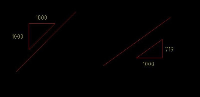
Hi guys, hopefully a pretty simply one here. I was just wondering if anyone has a routine (or knows of one) which will create a 'bevel' symbol/dimension similiar to the one shown in the attached image? Im not certain that im using the correct terminology to describe the dimension type - and i have tried a bit of googling with little luck (not knowing exactly how to describe what i was looking for). So... does anyone know of a routine which would create such a symbol? or of there is another method i can use? Thanks so much for any help.
-
I'm having trouble displaying the units for dimensions. The issue is with the suffix. When I add the " suffix to indicate inches autocad also adds the suffix to the angular dimension. 2 questions... Is there a way to suppress the suffix for angular dimensions? Do I need to have a dimension style just for angular dimension? I do not want to dimension in architectural because I don't want the dimensions to change to feet and inches.
-
i am new to this forum ...... i am using autocad2008, my boss wants me to draw a square 100x100mm in such a way so that if i take a print out in an A4 sheet(210x297mm) it should measure exactly 100mmx100mm wen i measure it using tape..... plz help i can't seem to figure this out ...
-

Placing Diamter Leaders - Why set length for leader? (2 part question)
ILoveMadoka posted a topic in AutoCAD 2D Drafting, Object Properties & Interface
Autocad 2012 Part I When I place a diameter/radius leader, it is a set length. I can move it all around the circle I'm dimensioning but the length of this leader is set. It is really short and it sucks to have to place the dimension then move it to where I want it as a second step. Is there a setting that will allow me to drag this dimension where I want and make the leader as long as I desire? Part II: In Autocad 2009, if you wanted to change a leader location, you could pick the text grip and it would move the end of the leader to that point then place the dimension from that point. Now picking the grip places the text and I have no control over the angle of the leader (our standards require leaders to always be a set angle from the object!) PLEASE advise!! Thanks! -

Map units is in inches, I want it in feet. How do I change this?
KariCad posted a topic in AutoCAD Beginners' Area
I am drawing a plan view of building that is 11 feet by 36 feet. I thought my map units were in feet but when I draw in the linear dimensions, it reads 11 inches x 3 feet. How do I change this? -
 I have a drawing of a factory, with different equipment foundations laid out. I'm trying to do a type of surveying, get a distance and angle measurement from a specific set point in the drawing. So far i've only been able to use the Aligned Dimension function to show the distance between the set point and edge of a foundation (for example.) How can I show the angle as well on the same dimension line. Any help would be REALLY appreciated!
 -

Very slow properties CAD on a decent machine
ColinPearson posted a topic in AutoCAD 2D Drafting, Object Properties & Interface
Hi all, I would appreciate any help I could get on this matter. I'm running CAD2011, a pretty good flavor of an i5, 8GB, Win7x64, 1GB graphics, etc... a nice-enough laptop for sure that CAD should be run seamlessly. HOWEVER! When I select a dimension, it takes at least 5 seconds for the properties box to correctly display and populate, then another few seconds once I click inside the box to be able to scroll/operate a drop down, type, etc. I have seen this posted with no resolution before... can anyone offer any advice on this matter? I saw one poster mention reloading support files such as fonts that may be corrupted but I must concede that I don't know exactly how to do this i.e, where would I get another copy of all of my fonts? -
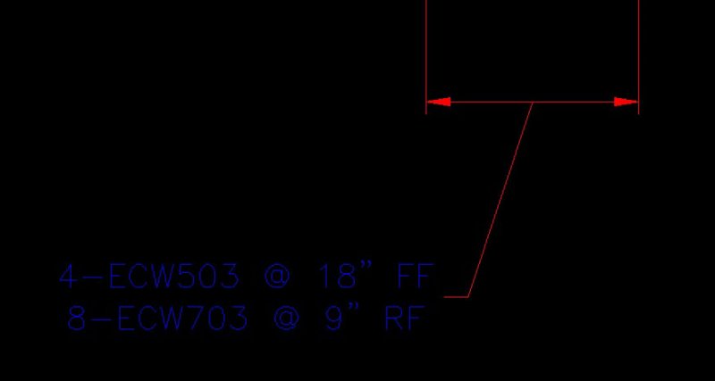
Pictures will best describe the problem I'm having. Autocad 2011 makes this: This is what I want: Pleas excuse the crappy photoshop job. but notice that the text bottom line is aligned to the middle of the leader landing and the text is left justified. Is there a way to make autocad's dimensioning do this automatically without me having to explode them and move them myself?