Search the Community
Showing results for tags 'lisp'.
-
 Hello guys, I am working in AutoCAD. I am looking for a combined LISP code for creating points for the selected objects at its Endpoints, Midpoints, Center, Geometric center, Node, Quadrant, Intersection & Insertion as per users requirements (options with drop down list mentioning Endpoints, Midpoints, Center, Geometric center, Node, Quadrant, Intersection & Insertion Shall get prompted.) Once I select the required snap then the result shall be creation of points at the chosen object snap. An imaginary Example shall be Like like this, command: POBS(Points at Object Snap)-->prompting for what snap need to be found in the selected objects in the for of drop down list--> Creating points in the selected Object Snaps of the selection set. Actually i had found few LISP codes for the following cases 1.PLE-Points on Line Ends.lsp 2.PAI-Point At Intersection.lsp Thanks for the authors of these above LISP they have saved lot of time till date. Thanks in advance.
 -

Autolisp giving error: bad argument type: "LINE" when trying to get line type
Erroreki posted a topic in AutoLISP, Visual LISP & DCL
Hi! Avid reader of the forums, first time poster. I have a code with which I'm trying to extract the x and y coordinate of the startpoint of a line to the clipboard for pasting into another program. The problem is that when I run the lisp in Civil 3D it spits out when running (caddr typelst) on line 6 in the code below. What could cause this. I'm having trouble understanding why it wouldn't be able to grab the type from the list. The code: (vl-load-com) (defun c:copyx1y1 () (setq choice (entsel "Choose the line whose start X and Y you want to copy \n")) (setq entname (car choice)) (setq typelst (assoc 0 (entget entname))) (if (= (caddr typelst) "LINE") (progn (setq startpnt (assoc 10 (entget entname))) (setq x1 (cadr startpnt)) (princ "\n") (princ x1) (princ "\n") (setq y1 (caddr startpnt)) (princ y1) (setq copiedtxt (strcat (rtos x1) "\t" (rtos y1))) (setq result (vlax-invoke (vlax-get (vlax-get (setq htmlfile (vlax-create-object "htmlfile")) 'ParentWindow) 'ClipBoardData) 'SetData "Text" copiedtxt) ) (vlax-release-object htmlfile) copiedtxt ) (progn (princ "The choice is not of type LINE") ) ) (princ) ) Regards, E -
LISP for Selection of alternate lines from the selection set of lines like 1st, 3rd, 5th, .....etc lines in autocad.
Pranesh Rathinam posted a topic in AutoLISP, Visual LISP & DCL
Hello guys, I am new to this forum. I need LISP for Selection of alternate lines from the selection set of lines like 1st, 3rd, 5th, .....etc lines in Autocad. I am attaching the file with my requirement. Alternate Selection of lines.dwg Please help me out with an possible lisp solution. Also, Is there a Autocad Plugin to do this? If so Please share the link Thanks in advance, Pranesh Rathinam -
Hi Guys I have a .dwt with all of my custom blocks, leaderstyles, dimstyles and textstyles. i have allot of custom lisp files that generates custom styles and leaders using my styles that i have set up in my .dwt file. I have found that if i work on a drawing from another person and i want to use my "custom" lisp commands i have to drag in my styles via design center. is there a way of adding these styles automatically from my .dwt into the current drawing via lisp? then i can just edit my lisp files to include this instead of dragging in styles from my own template file?
-
Dear team , I used etransmit command >add file than bind xref option, but not bind in current drawing. Is any tools or lisp, VBA macro for add multiple xref and bind together in current file and save as a zip file.? Note :, Xref not attached in current drawing. I need to attach multiple and bind together in current drawing. Thanks
-

Can any one teach me how to make USB lisp with password??? plssss
bunhoc_hh posted a topic in AutoLISP, Visual LISP & DCL
So i make some lisp-cover them to fas. Put all in 1 folder and make 1 mnu file that load with menuload and load all that lisp. But now i want put that in USB and when i load it to autocad, whatever i click in any lisp i want password showup then when i enter password i can use all fuction of it. Every time i open autocad and use them i need reenter password. Any change i can make that? -

Request: Lisp command that can quick swap text between two objects
plackowski posted a topic in AutoLISP, Visual LISP & DCL
I'm looking for a lisp command that can quick swap text between two objects, be they text, mtext, or multi-leader text. So upon running, you click on the two objects, and the text from object A moves to object B, and the text from object B moves to object A, where object A and object B can be different object types. -

_ColorOffsetV031 Unknown command "COLOROFFSETV031". Press F1 for help.
AM-AP posted a topic in AutoLISP, Visual LISP & DCL
Hi there, I'm AM and new to the forum I'm creating a set of easy lisp routines for my team. I've loaded the following lisp file into AutoCAD and it works fine when typing the function ColorOffsetV031 into the command line within AutoCAD. However, when I try create a new command that will run the lisp with a macro like ^C^CColorOffsetV031 or ^C^C_ColorOffsetV031 so I can then add it to a ribbon/tab/tool palette, I get the following error: "_ColorOffsetV031 Unknown command "COLOROFFSETV031". Press F1 for help." I'm honestly not sure what I'm doing wrong. I've tried different ways of loading the lisp file, from just dropping the file into AutoCAD, adding it to the Startup Suite, loading it as an application etc. I've created 'buttons' like this before, and I feel so silly asking such a simple question; It's probably something really simple that I just can't pick up on... Even if someone can point me in the direction of a related post from someone else I would be very grateful The lisp: ; Define the tool/function name and variables (defun C:ColorOffsetV31 ( / EName EInfo EColor Group ans ansColor) (setvar "CMDECHO" 1) ; Set the options for user choice (initget "Orange Red Yellow Green Cyan Blue Magenta White L-Grey") ; Ask for user input on color for offset (setq ans (cond ((getkword "\nChoose offset object color [Orange/Red/Yellow/Green/Cyan/Blue/Magenta/White/L-Grey] or ENTER for Orange")) ("Orange"))) ; Set ansColor as input color (cond ((= ans "Orange") (setq ansColor 30)) ((= ans "Red") (setq ansColor 1)) ((= ans "Yellow") (setq ansColor 2)) ((= ans "Green") (setq ansColor 3)) ((= ans "Cyan") (setq ansColor 4)) ((= ans "Blue") (setq ansColor 5)) ((= ans "Magenta") (setq ansColor 6)) ((= ans "White") (setq ansColor 7)) ((= ans "L-Grey") (setq ansColor 8)) ; Should not happen but just here incase no input is given, set ansColor to BLACK (t (setq ansColor 250)) ) ;----------------------------- ; Start OFFSET (command "OFFSET" pause) ; Do the following with OFFSET (while (= 1 (logand 1 (getvar "CMDACTIVE"))) (command pause) ; While OFFSET command is on (while (= 1 (logand 1 (getvar "CMDACTIVE"))) (command pause) ; Set the current entity to be used as the last clicked entity (setq EName (entlast)) ; Get entity info (setq EInfo (entget EName)) ; If the colour of the object isn't known (if (not EColor) ; Match ans to EColor (setq EColor ansColor) ) ; Change the colour (entmod (append EInfo (list (cons 62 EColor)))) ) ) (setvar "CMDECHO" 0) (princ) ) Here's a copy of the command itself too Thanks, AM
-
Hello to everyone! I wand to create a lisp file that prints on a loop while hiding and unhiding different layers. I am working on a cad software called 4MCAD. 4MCAD unfortunately does not have the native Autocad DWGtoPDF printer. The main problem I am facing is that I have to use third party printers to plot to PDF which ask for the name of the PDF file name on a seperate window. I have tried Nitro PDF creator, cutePDF, doPDF and I cannot figure out how to supress the pop-up window while giving the desired name to the PDF file. Has anyone know how to solve this problem? Can you get DWGtoPDF printer as system printer so my Cad software can find it? Has anyone suceeded with any third party software at giving the file name inside the lisp file? For example let's say that the desired filename is "C:\DWG_prints\DWGpr1.pdf" and I want a command like this: (command "-plot" "n" "" "" "" "n" "n" "" "C:\DWG_prints\DWGpr1.pdf" )
-
Hi Experts, I downloaded the Chainage Lisp created by hak_vz. In their code, chainage is plotted with an interval. However, I would like to obtain the chainage when I click on an intersection point or anywhere on the selected polyline. Could you please help me with this? I have also attached the Lisp file for reference. chainage_hak_vz.lsp
-

Copy Multiple Block Attributes from one block to another one click
lamonmar posted a topic in AutoLISP, Visual LISP & DCL
I have a drawing that has two different blocks (see attached), what I needed to do was transfer over the attributes of one block over to the other (both have different tags). For example copying over attributes in "rev0_date" from the first block tag over to "revslot1date" in the second block tag , I ran across some code in the forums that did just that created by Lee Mac.The problem with it is it only transfers one attribute over, I modified it a little but its still not exactly what I need. The way it currently works is - It asks me to choose the first block with the attributes to copy, once selected it then asks me to choose the second block that will have the attributes pasted to it, once I've selected them, it then pastes the first specified tag attribute in the first block to the second, after that I have to repeat the process again, clicking the block with the attribute to copy and then choosing the second block to paste, I have to keep repeating these steps, clicking the first block then the second over and over until all the tag attributes have been copied over. My question is how can I stop having click the first and then second block over and over again for each tag and instead only have to go through the process once (click first block, then second and then transfer all the attributes over at once). Here is my current code (sorry if its a mess I'm very new to this): (defun c:blockswap ( / _SelectBlockWithTag a b des src tag ) (vl-load-com) (setq DAT1A "Rev0_Date" ; Source Attribute Tag 1 DES1A "Rev0_Desc" ; Source Attribute Tag 2 REV1A "Rev0" ; Source Attribute Tag 3 RDB1A "Rev0_Drawn_By" ; Source Attribute Tag 4 REV1B "RevSlot1Number" ; Destination Attribute Tag 3 DES1B "RevSlot1Description" ; Destination Attribute Tag 2 DAT1B "RevSlot1Date" ; Destination Attribute Tag 1 RDB1B "RevSlot1DrawnBy" ; Destination Attribute Tag 4 ) (defun _SelectBlockWithTag ( tag / e a ) (setq tag (strcase tag)) (while (progn (setvar 'ERRNO 0) (setq f (car (entsel (strcat "\nSelect Block with attribute " tag ": ")))) (cond ( (= 7 (getvar 'ERRNO)) (princ "\nMissed, Try Again.") ) ( (not f) nil ) ( (and (eq "INSERT" (cdr (assoc 0 (entget f)))) (= 1 (cdr (assoc 66 (entget f)))) ) (if (not (setq z (vl-some (function (lambda ( x ) (if (eq tag (strcase (vla-get-tagstring x))) x) ) ) (vlax-invoke (vlax-ename->vla-object f) 'getattributes) ) ) ) (princ (strcat "\nBlock does not contain tag " tag ".")) ) ) ( (princ "\nInvalid Object Selected.") ) ) ) ) z ) (and (setq aa (_SelectBlockWithTag DAT1A)) (setq ab (_SelectBlockWithTag DAT1B)) ) (vla-put-textstring ab (vla-get-textstring aa)) (and (setq ba (_SelectBlockWithTag DES1A)) (setq bb (_SelectBlockWithTag DES1B)) ) (vla-put-textstring bb (vla-get-textstring ba)) (and (setq ca (_SelectBlockWithTag REV1A)) (setq cb (_SelectBlockWithTag REV1B)) ) (vla-put-textstring cb (vla-get-textstring ca)) (and (setq da (_SelectBlockWithTag RDB1A)) (setq db (_SelectBlockWithTag RDB1B)) ) (vla-put-textstring db (vla-get-textstring da)) (princ) ) drawing.dwg -
At my job, i have a very tedious job of changing layers from proposed to existing and vice versa our layer setup is very basic "LayerName"=existing layer "LayerName-PR"=Proposed layer. i have recently bought a book to to learn AutoLisp and I've gotten the basic concept. I know that i want to ssget LayerName and setq that name to L then CHPROP LA to L-PR. but i want to know if someone has anything like this already and could help me. I'd like to do a mass select and have it automatically change the entities to their respective PR layer. also vice versa, to remove PR. i'm not looking for a layer renaming lisp. i'm looking for a entity layer changing lisp. anything helps. thanks.
-
I wanted a command to close and not to save. I used the following code: (defun c:cln () ;Close No save (setvar "cmdecho" 0) (command "close" "No") (setvar "cmdecho" 1) ) But when I use it, it closes and saves.....help :S
-
 I want to add another layer to my routine to allow saving of layer state for On/off, Lock, Freeze, and restore them back after routine. I got the locked layer part but i could not understand this awesome crazy simple routine by Kent1Copper from Autodesk Forum (defun GLL (/ lay); = Get Locked Layers (while (setq lay (tblnext "layer" (not lay))) (if (= (logand (cdr (assoc 70 lay)) 4) 4); locked (setq LockedLayers (strcat (cond (LockedLayers) ("")) (cdr (assoc 2 lay)) ",")) ); if ); while ); defun (defun UAL (); = Unlock All Layers (command "_.layer" "_unlock" "*" "") ); defun (defun RLL () ; = Relock [formerly] Locked Layers (command "_.layer" "_lock" LockedLayers "") ); defun Basically, I do not understand this part of code below, where and how it capture the lock/unlock layer state and how i can capture the on/off & freeze layer state (while (setq lay (tblnext "layer" (not lay))) (if (= (logand (cdr (assoc 70 lay)) 4) 4); locked (setq LockedLayers (strcat (cond (LockedLayers) ("")) (cdr (assoc 2 lay)) ",")) ); if ); while Many thanks in advance.
 -
Hello to everyone. I have a file that can draw the longitudinal path of a water line, but it lacks some technical details, such as drawing the boundaries of the table beneath the chart and signing the depth calculated by the lisp as it is, rather than minus a distance estimated by the pipe's radius. Please seek assistance from people with relevant experience. Attachment: Assign Excel and Lisp next to a CAD file that almost has a work model with some notes. WATER PROFILE SPREADSHEET.xlsx TEST PROFILE NOT COMPLETING DRAWING BY LISP AND XLS.dwg WaterProfile.LSP
-

Copy a pipe Network item from XREF to current Drawing as Polyline
RamboGT posted a topic in AutoLISP, Visual LISP & DCL
I'm trying to figure out how to write a LISP command where I can click on multiple pipe network pipes from an XREF, and it copies them into my current drawing on the current layer, changing the linetype to contiguous, color to ByLayer, and seta global width of 1. Current theory on how this 'might' be accomplished: -click on xref pipe network pipe -it ncopy's item with base point 0,0 -explode items -burst items -set global width of all items to 1 -change linetype to contiguous for all items -change layer to current layer for all items -join all items that are touching (create one polyline from a group of pipe network pipe items) Thoughts? Thanks. --Matt -
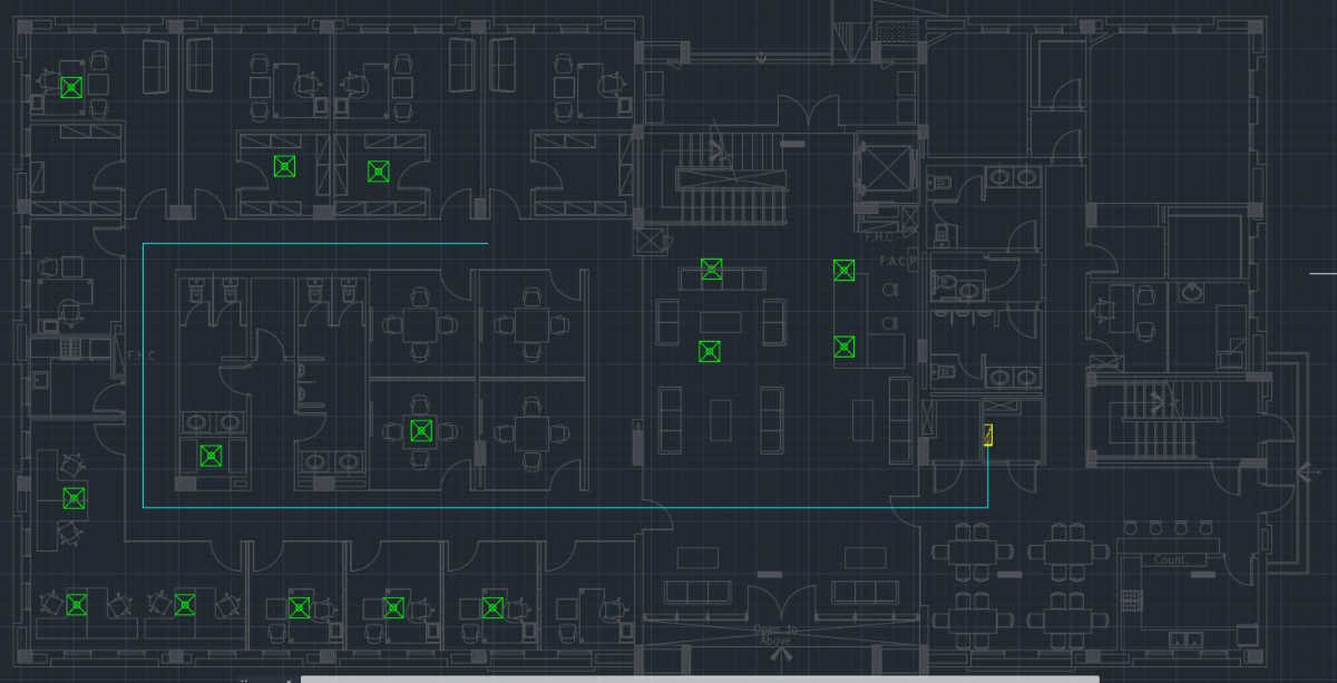
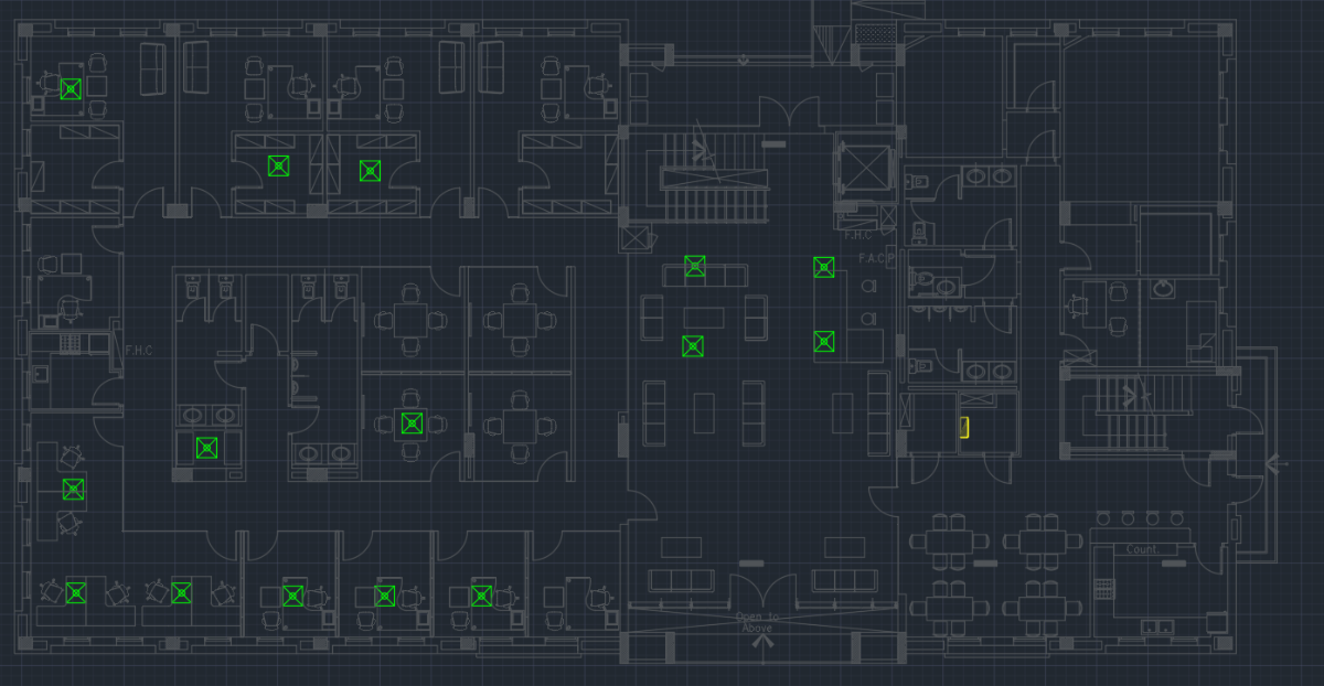
hello i want help for creating lisp for me please ... the lisp will do these functions 1- as the attached image (1a) if i have block with yellow at right and some green blocks 2- i want when i launch the lisp to ask me to draw poly line that i want as in image 2a 3- after that when i draw this path with polyline and press enter the lisp ask me to choose blocks that i want to connect to this polyline and i will choose one by one or multiple blocks then after choosing the blocks and press enter ... the lisp will offset the main polyline that i draw and connect every polyline with the basepoint of the blocks that i choose sequentially as appear in this image 5a (attached DWG) can anyone help me please sample.dwg
- 10 replies
-
- 1
-

-
- visual lisp
- visuallisp
- (and 3 more)
-

Need help to put quantities to specific excel file.
m1r posted a topic in AutoLISP, Visual LISP & DCL
Greetings my friends I need some help with this lisp, this lisp (Medz v3.lsp) it basically makes a measurement of all lines arc and put the results in an new excel file divided by layer, linetype, color and length, this lisp works well but i need help to make the follow a modification: I need that the results to be in a specifc excel file (see attach xlsx file) on the "MED AUX" tab with the range A11:D11, it seems a simple modification, but i don't have the knowledge to do it. Many thanks MedZ v3.lsp Mede Aux.xlsx -
Hi! I have this code that i found here in the forum it was created by @rlx. My question is how to add an automatic current date and time to the end of the file when im saving it. Many thanks! xoxo (defun c:foo (/ _dir F NF P SF SH) (defun _dir (msg path / sh folder out) (or (vl-file-directory-p path) (setq path (getvar 'dwgprefix))) (cond ((and (setq sh (vlax-get-or-create-object "Shell.Application")) (setq folder (vlax-invoke-method sh 'browseforfolder 0 msg "&H2000" path)) ) (setq out (vlax-get-property (vlax-get-property folder 'self) 'path)) (setq out (strcat (vl-string-right-trim "\\" out) "\\")) ) ) (and sh (vlax-release-object sh)) out ) (if (setq p (_dir "Pick a directory yo!" "E:\\Autocad Files\\SSC\\North Region\\SNE\\")) (progn (setq f (getvar 'dwgname)) (setq sf "Plans") (setq nf (strcat p sf "\\" f)) (cond ((cond ((findfile nf) (print "File exists...") nil) ((vl-file-directory-p (strcat p sf)) (vl-file-copy (strcat (getvar 'dwgprefix) f) nf) t) ((vl-mkdir (strcat p sf)) (vl-file-copy (strcat (getvar 'dwgprefix) f) nf) t) ) (setq sh (vlax-get-or-create-object "Shell.Application")) (vlax-invoke-method sh 'open nf) (vlax-release-object sh) ) ) ) ) (princ) ) (vl-load-com)
-
i need lisp program like fillet or join as mention attached pic.
-

Simple LISP to draw a cross from lower left to upper right corners
Eiler posted a topic in AutoLISP, Visual LISP & DCL
Hi, I havent done much of AutoCAD LISP writing, and certainly not for many years now, but I was trying to figure out how to make a simple function that would draw a cross with 2 diagonal lines, from lower left corner PT1 to upper right corner PT2. I thought it might be possible to draw a -pline from PT1(X1,Y1) - PT2(X2,Y2) -second pline from (X1,Y2) - (X2,Y1) This would save me time drawing different size crosses by letting me draw 2 diagonal line by clicking just two points could anyone help me with a code for this? -
Hello, I was getting a drawing that I have to modify. The problem is, that in this drawing are several block references with the name. I.e. I have about 100 block references calling "WcLux" . Is there a possibility to make the name of the block reference unique with a script: WcLux_1, WcLux2, ... WcLux100 Thx Frank
-

How to use Wire Copy (AECOPYWIRENO / WD_COPY_WN) in LISP
NicholasCAD posted a topic in AutoLISP, Visual LISP & DCL
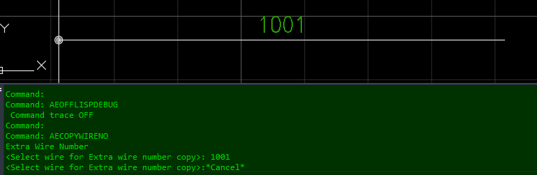
(Hopefully this Question has not been asked. The Search gave no Results.) For Context: I have created a Program that generates a complex Component (Block, Wiring, Text) onto a Sheet. The Program uses .LSP and .DCL for ease of Use for our Operators. The Prompt has Options to configure the Component to any Options we need. Inquiry: I need to update the Program to include Wire Numbers and Wire Number Copies. (I will be trying to use "WD_PUTWNXY" Command for New Wire Networks, although I have yet to do so.) For Wire Number Copies, I was hoping to use either the "AECOPYWIRENO" or "WD_COPY_WN" Commands. The Problem with these Commands is that they do not allow for Coordinate Placement. When running either Command, the Command Line is requesting to select a Wire as an Entity. What I would like, is an example of a LISP that completes this Task using a Coordinate System to select and place the Wire Number Copies. Any Advice would be much appreciated!
-
Hello, I am new to LISP, I found the Area-to-Table LISP from Lee Mac, which is very useful, but I need it to write the area in the third column of the table instead of the second. I modified some parameters to create the third column and the first row of the table works, but the following rows don't. Also I would like to have the numbers that are inserted in the centroid in a circle, but this could be optional. The text should be 0.3 in height and the circle should have a 0.25 radius. I defined the style at the beginning, but the height does not work. I would be grateful for some help, thank you! This is the LISP: (defun c:Recap nil (AreaLabel t)) ;; Areas to Table ;start of sectin added to define text style (entmakex '( (0 . "STYLE") (100 . "AcDbSymbolTableRecord") (100 . "AcDbTextStyleTableRecord") (2 . "room_Style") (70 . 0) (40 . 0.3);<- text height defined (41 . 1.0) (50 . 0.0) (71 . 0) (42 . 2.0) (3 . "times.ttf") (4 . "") ) ) (setvar 'textstyle "room_Style") ; end of section added to define text style ;;------------------------------------------------------------;; (defun AreaLabel ( flag / *error* _startundo _endundo _centroid _text _open _select _getobjectid _isannotative acdoc acspc ap ar as cf cm el fd fl fo n of om p1 pf pt sf st t1 t2 t3 tb th ts tx ucsxang ucszdir ) ;;------------------------------------------------------------;; ;; Adjustments ;; ;;------------------------------------------------------------;; (setq h1 "Recap Table" ;; Heading t1 "Numer" ;; Number Title t2 "Room" ;;Area Name t3 "Area" ;; Area Title pf "" ;; Number Prefix (optional, "" if none) sf "" ;; Number Suffix (optional, "" if none) ap "" ;; Area Prefix (optional, "" if none) as "" ;; Area Suffix (optional, "" if none) cf 1.0 ;; Area Conversion Factor (e.g. 1e-6 = mm2->m2) fd t ;; Use fields to link numbers/objects to table (t=yes, nil=no) fo "%lu6%qf1" ;; Area field formatting ) ;;------------------------------------------------------------;; (defun *error* ( msg ) (if cm (setvar 'CMDECHO cm)) (if el (progn (entdel el) (setq el nil))) (if acdoc (_EndUndo acdoc)) (if (and of (eq 'FILE (type of))) (close of)) (if (and Shell (not (vlax-object-released-p Shell))) (vlax-release-object Shell)) (if (null (wcmatch (strcase msg) "*BREAK,*CANCEL*,*EXIT*")) (princ (strcat "\n--> Error: " msg)) ) (princ) ) ;;------------------------------------------------------------;; (defun _StartUndo ( doc ) (_EndUndo doc) (vla-StartUndoMark doc) ) ;;------------------------------------------------------------;; (defun _EndUndo ( doc ) (if (= 8 (logand 8 (getvar 'UNDOCTL))) (vla-EndUndoMark doc) ) ) ;;------------------------------------------------------------;; (defun _centroid ( space objs / reg cen ) (setq reg (car (vlax-invoke space 'addregion objs)) cen (vlax-get reg 'centroid) ) (vla-delete reg) (trans cen 1 0) ) ;;------------------------------------------------------------;; (defun _text ( space point string height rotation / text ) (setq text (vla-addtext space string (vlax-3D-point point) height)) (vla-put-alignment text acalignmentmiddlecenter) (vla-put-textalignmentpoint text (vlax-3D-point point)) (vla-put-rotation text rotation) text ) ;;------------------------------------------------------------;; (defun _Open ( target / Shell result ) (if (setq Shell (vla-getInterfaceObject (vlax-get-acad-object) "Shell.Application")) (progn (setq result (and (or (eq 'INT (type target)) (setq target (findfile target))) (not (vl-catch-all-error-p (vl-catch-all-apply 'vlax-invoke (list Shell 'Open target)) ) ) ) ) (vlax-release-object Shell) ) ) result ) ;;------------------------------------------------------------;; (defun _Select ( msg pred func init / e ) (setq pred (eval pred)) (while (progn (setvar 'ERRNO 0) (apply 'initget init) (setq e (func msg)) (cond ( (= 7 (getvar 'ERRNO)) (princ "\nMissed, try again.") ) ( (eq 'STR (type e)) nil ) ( (vl-consp e) (if (and pred (not (pred (setq e (car e))))) (princ "\nInvalid Object Selected.") ) ) ) ) ) e ) ;;------------------------------------------------------------;; (defun _GetObjectID ( doc obj ) (if (vl-string-search "64" (getenv "PROCESSOR_ARCHITECTURE")) (vlax-invoke-method (vla-get-Utility doc) 'GetObjectIdString obj :vlax-false) (itoa (vla-get-Objectid obj)) ) ) ;;------------------------------------------------------------;; (defun _isAnnotative ( style / object annotx ) (and (setq object (tblobjname "STYLE" style)) (setq annotx (cadr (assoc -3 (entget object '("AcadAnnotative"))))) (= 1 (cdr (assoc 1070 (reverse annotx)))) ) ) ;;------------------------------------------------------------;; (setq acdoc (vla-get-activedocument (vlax-get-acad-object)) acspc (vlax-get-property acdoc (if (= 1 (getvar 'CVPORT)) 'Paperspace 'Modelspace)) ucszdir (trans '(0. 0. 1.) 1 0 t) ucsxang (angle '(0. 0. 0.) (trans (getvar 'UCSXDIR) 0 ucszdir)) ) (_StartUndo acdoc) (setq cm (getvar 'CMDECHO)) (setvar 'CMDECHO 0) (setq om (eq "1" (cond ((getenv "LMAC_AreaLabel")) ((setenv "LMAC_AreaLabel" "0"))))) (setq ts (/ (getvar 'TEXTSIZE) (if (_isAnnotative (getvar 'TEXTSTYLE)) (cond ( (getvar 'CANNOSCALEVALUE) ) ( 1.0 )) 1.0 ) ) ) (cond ( (not (vlax-method-applicable-p acspc 'addtable)) (princ "\n--> Table Objects not Available in this Version.") ) ( (= 4 (logand 4 (cdr (assoc 70 (tblsearch "LAYER" (getvar 'CLAYER)))))) (princ "\n--> Current Layer Locked.") ) ( (not (setq *al:num (cond ( (getint (strcat "\nSpecify Starting Number <" (itoa (setq *al:num (1+ (cond ( *al:num ) ( 0 ))))) ">: " ) ) ) ( *al:num ) ) ) ) ) ( flag (setq th (* 2. (if (zerop (setq th (vla-gettextheight (setq st (vla-item (vla-item (vla-get-dictionaries acdoc) "ACAD_TABLESTYLE" ) (getvar 'CTABLESTYLE) ) ) acdatarow ) ) ) ts (/ th (if (_isAnnotative (vla-gettextstyle st acdatarow)) (cond ( (getvar 'CANNOSCALEVALUE) ) ( 1.0 )) 1.0 ) ) ) ) ) (if (cond ( (progn (initget "Add") (vl-consp (setq pt (getpoint "\nPick Point for Table <Add to Existing>: "))) ) (setq tb (vla-addtable acspc (vlax-3D-point (trans pt 1 0)) 2 3 th (* 1.2 th (max (strlen t1) (strlen t2) (strlen t3))) ;chage tabel row, column, column height ) ) (vla-put-direction tb (vlax-3D-point (getvar 'UCSXDIR))) (vla-settext tb 0 0 h1) (vla-settext tb 1 0 t1) (vla-settext tb 1 1 t2) (vla-settext tb 1 2 t3) (while (progn (if om (setq p1 (_Select (strcat "\nSelect Object [Pick] <Exit>: ") '(lambda ( x ) (and (vlax-property-available-p (vlax-ename->vla-object x) 'area) (not (eq "HATCH" (cdr (assoc 0 (entget x))))) (or (eq "REGION" (cdr (assoc 0 (entget x)))) (vlax-curve-isclosed x)) ) ) entsel '("Pick") ) ) (progn (initget "Object") (setq p1 (getpoint "\nPick Area [Object] <Exit>: "))) ) (cond ( (null p1) (vla-delete tb) ) ( (eq "Pick" p1) (setq om nil) t ) ( (eq "Object" p1) (setq om t) ) ( (eq 'ENAME (type p1)) (setq tx (cons (_text acspc (_centroid acspc (list (setq p1 (vlax-ename->vla-object p1)))) (strcat pf (itoa *al:num) sf) ts ucsxang ) tx ) ) (vla-insertrows tb (setq n 2) th 1) (vla-settext tb n 2 ;changed here from 1 to 2 (if fd (strcat "%<\\AcObjProp Object(%<\\_ObjId " (_GetObjectID acdoc p1) ">%).Area \\f \"" fo "\">%" ) (strcat ap (rtos (* cf (vla-get-area p1)) 2) as) ) ) (vla-settext tb n 0 (if fd (strcat "%<\\AcObjProp Object(%<\\_ObjId " (_GetObjectID acdoc (car tx)) ">%).TextString>%" ) (strcat pf (itoa *al:num) sf) ) ) nil ) ( (vl-consp p1) (setq el (entlast)) (vl-cmdf "_.-boundary" "_A" "_I" "_N" "" "_O" "_P" "" "_non" p1 "") (if (not (equal el (setq el (entlast)))) (progn (setq tx (cons (_text acspc (_centroid acspc (list (vlax-ename->vla-object el))) (strcat pf (itoa *al:num) sf) ts ucsxang ) tx ) ) (vla-insertrows tb (setq n 2) th 1) (vla-settext tb n 1 (strcat ap (rtos (* cf (vlax-curve-getarea el)) 2) as)) (vla-settext tb n 0 (if fd (strcat "%<\\AcObjProp Object(%<\\_ObjId " (_GetObjectID acdoc (car tx)) ">%).TextString>%" ) (strcat pf (itoa *al:num) sf) ) ) (redraw el 3) nil ) (vla-delete tb) ) ) ) ) ) (not (vlax-erased-p tb)) ) ( (and (setq tb (_Select "\nSelect Table to Add to: " '(lambda ( x ) (eq "ACAD_TABLE" (cdr (assoc 0 (entget x))))) entsel nil ) ) (< 1 (vla-get-columns (setq tb (vlax-ename->vla-object tb)))) ) (setq n (1- (vla-get-rows tb)) *al:num (1- *al:num)) ) ) (progn (while (if om (setq p1 (_Select (strcat "\nSelect Object [" (if tx "Undo/" "") "Pick] <Exit>: ") '(lambda ( x ) (and (vlax-property-available-p (vlax-ename->vla-object x) 'area) (not (eq "HATCH" (cdr (assoc 0 (entget x))))) (or (eq "REGION" (cdr (assoc 0 (entget x)))) (vlax-curve-isclosed x)) ) ) entsel (list (if tx "Undo Pick" "Pick")) ) ) (progn (initget (if tx "Undo Object" "Object")) (setq p1 (getpoint (strcat "\nPick Area [" (if tx "Undo/" "") "Object] <Exit>: "))) ) ) (cond ( (and tx (eq "Undo" p1)) (if el (progn (entdel el) (setq el nil))) (vla-deleterows tb n 1) (vla-delete (car tx)) (setq n (1- n) tx (cdr tx) *al:num (1- *al:num)) ) ( (eq "Undo" p1) (princ "\n--> Nothing to Undo.") ) ( (eq "Object" p1) (if el (progn (entdel el) (setq el nil))) (setq om t) ) ( (eq "Pick" p1) (setq om nil) ) ( (and om (eq 'ENAME (type p1))) (setq tx (cons (_text acspc (_centroid acspc (list (setq p1 (vlax-ename->vla-object p1)))) (strcat pf (itoa (setq *al:num (1+ *al:num))) sf) ts ucsxang ) tx ) ) (vla-insertrows tb (setq n (1+ n)) th 1) (vla-settext tb n 1 (if fd (strcat "%<\\AcObjProp Object(%<\\_ObjId " (_GetObjectID acdoc p1) ">%).Area \\f \"" fo "\">%" ) (strcat ap (rtos (* cf (vla-get-area p1)) 2) as) ) ) (vla-settext tb n 0 (if fd (strcat "%<\\AcObjProp Object(%<\\_ObjId " (_GetObjectID acdoc (car tx)) ">%).TextString>%" ) (strcat pf (itoa *al:num) sf) ) ) ) ( (vl-consp p1) (if el (progn (entdel el) (setq el nil))) (setq el (entlast)) (vl-cmdf "_.-boundary" "_A" "_I" "_N" "" "_O" "_P" "" "_non" p1 "") (if (not (equal el (setq el (entlast)))) (progn (setq tx (cons (_text acspc (_centroid acspc (list (vlax-ename->vla-object el))) (strcat pf (itoa (setq *al:num (1+ *al:num))) sf) ts ucsxang ) tx ) ) (vla-insertrows tb (setq n (1+ n)) th 1) (vla-settext tb n 1 (strcat ap (rtos (* cf (vlax-curve-getarea el)) 2) as)) (vla-settext tb n 0 (if fd (strcat "%<\\AcObjProp Object(%<\\_ObjId " (_GetObjectID acdoc (car tx)) ">%).TextString>%" ) (strcat pf (itoa *al:num) sf) ) ) (redraw el 3) ) (princ "\n--> Error Retrieving Area.") ) ) ) ) (if el (progn (entdel el) (setq el nil))) ) ) ) ) (setenv "LMAC_AreaLabel" (if om "1" "0")) (setvar 'CMDECHO cm) (_EndUndo acdoc) (princ) ) ;;------------------------------------------------------------;; ;; End of File ;; ;;------------------------------------------------------------;;
-
hi can anyone here help write a lisp routine that can be run project wide to hide/show attributes . The user must be given an option to select an object , write or select attribute name and also select multiple drawings from the project. I have a code that updates the attribute value , attaching that - Please help change that to hide/show attributes updateATTRIB.lsp