Search the Community
Showing results for tags 'scale'.
-

Dimention text cannot be scaled.
CADPOLE posted a topic in AutoCAD 2D Drafting, Object Properties & Interface
Background Info: I am fixing about 10 drawings with to our clients standards, which are no where close to normal drafting standards. This client likes their titleblocks droped in to model space and scaled to fit, unless it has multiple scales on the drawing then it's O.K. to do it the correct way. I know right!! Anyway I am trying to get some drawings ready for IFC. The problem: The person that set these dwg's up did the dimentions in paperspace and now that I have them in model space I can't get the text size to change. I can't change them in dimention style format box because it is grey'd out. I tried to change the overall scale in the dim style box to no avail. I also tried highlighting and changing the text size in the properties box but alas that to failed. I would ask the guy but he has been out sick for a week. Anyone got any ideas? -

Scaling of Inserted Blocks
aisoos posted a topic in AutoCAD 2D Drafting, Object Properties & Interface
Hey Everyone, I'm having a problem, I created a block w/ attributes for my border and saved it for future use on other drawings. But when I insert it, even if the units are the same the blocks I inserted scaled smaller than the actual border that i wanted it to be. Anyone able to help me please -
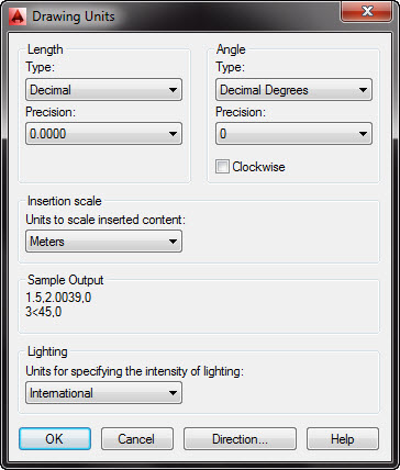
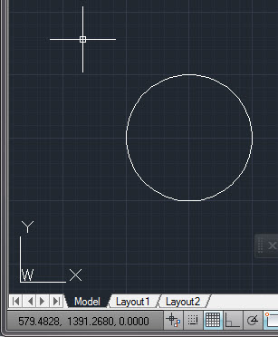
I set up a new page thus (I live in a country which uses metric units, so ...): Then: Command: '_limits Reset Model space limits: Specify lower left corner or [ON/OFF] : 0.00,0.00 Specify upper right corner : 3.65,2.74 Command: C CIRCLE Specify center point for circle or [3P/2P/Ttr (tan tan radius)]: 1000,1000 Specify radius of circle or [Diameter]: 250 Command: and I get: The circle was centred at x=1000 metres, y=1000 metres, yet it displays right down at the bottom left of my screen. Compare the radius of the circle to the distance from the centre to the origin - it's nothing like 1:4! Look at the coordinates for the cursor! Zooming in and zooming out has no effect on the huge dimensions indicated by the coordinates. I know this must be simple because it is not mentioned in any textbook or tutorial I have been able to find. Authors don't seem to think it is important, but it's driving me nuts! The question is this: How do I set the page size and grid scale to something sane? I am pretty sure that this scale problem is at the root of many of the other problems I am having. A14 is doing it's job faithfully but the display is so small that I cannot see what is happening ! All assistance much appreciated.

-
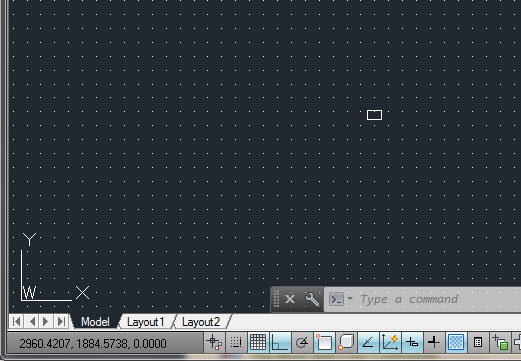
I have started Brian Benton's tutorials and hit a problem on the second one, "Quick Run Thru". The problem is that the object drawn is too small on the screen to be useful. This was the result of drawing the 50x30 rectangle called for in the tutorial. What setting adjustment is required to show the rectangle as it appears in the tutorial - i.e. larger on the screen so I can do something with it. Thanks
-
I am trying to draw an octagonal luminaire arm with a slight taper for a light pole by sweeping along a polyline profile. Sometimes it lets me do it, most of the time it doesn't. I can do a scaled sweep along a straight path and an unscaled sweep along a curved path, but I cannot do a scaled sweep along a curved path. I've spent hours on this and can't seem to figure this one out. What am I missing?
-
A guy I work with has jacked something up and I can't find a fix. He XREF'd in something that I KNOW the scale is 1:1. We've been using this main drawing for quite some time. However, when he brings it in, his dimensions are making it weird. What should be 20 feet is now 20 inches. What should be 4 feet is now 4 inches...what in the world?!?!?!
-

metric scaling viewport
jacktopus posted a topic in AutoCAD 2D Drafting, Object Properties & Interface
I have been looking through a ton of threads and can only find half an answer to what I'm looking for: When I draw in mm, I have to set the scale of the viewport to 1:30 or somewhere in that range. But in reality, the object that Im drawing isn't 1/30th of the size that it prints. How do I get the scale right to print the object at its actual size? cad 2013 sorry if its a noob question -
Hi folks I have a floor plan of residential building. In modeling mode the ratio is 1:1, after I fitted the drawing to my viewport in layout mode, the ratio is lets say 1:50. Does this effect my dimension? I used metric unit (Centimeter), because I thought when someone reads my drawing, he will count each 1 unit as 50 which I dont want. I know it sounds kinda rookie, bu pls som1 give some hands
-
Hi, I received a site plan for my house in an unknown scale. It is in 1'=100' scale printed on 24x36, but for some reason I cannot work with it in AutoCAD 2009. I'm trying to place my 1'=30' scale house on the site plan, but the house is ending up gigantic and not to scale. TutorCAD.dwg
-
Hi, For an autocad assignment, we have been given a drawing in engineering notation (feet and inches) and have to draw it with SI units dimensions. Doing the drawing was fine, BUT, I drew it in inches and thought that I could change it to millimetres. I have used the units command initially to set up engineering. Then after drawing returned to units to change to decimal. Dimensions turned out in inches regardless. I also tried the scale command to alter the scale, then dimension , still no luck. I went into the annotation menu got to modify primary units and alternate units and still no luck. Could someone please help. Not even my tutorial teacher knows how to do this.
-

Lay-out doesn't scale right
progvincent posted a topic in AutoCAD 2D Drafting, Object Properties & Interface
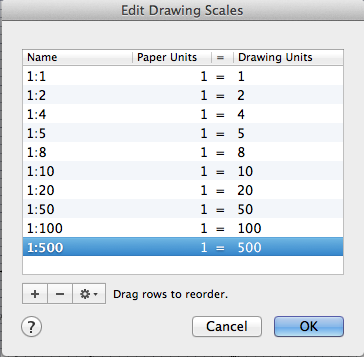
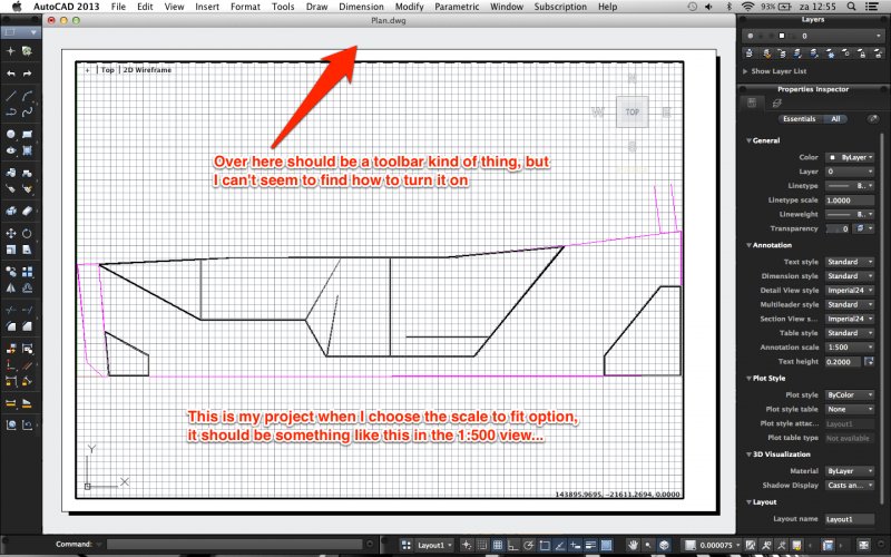
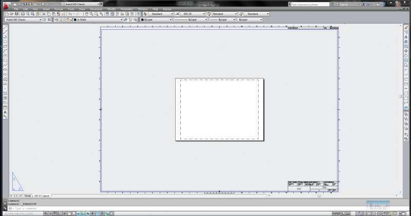
Hi, I've got a drawing of a site, which is about 144 meter long, so 144000 mm to put it in autocad units. I drew it completely in millimeters, and made a new scale in the layout view 1:500, all my units are set to millimeters. I would expect when chosing the scale 1:500 it would precisely fit on my paper, as 144000/500=288 and the longest side of an A4 paper is 297. But somehow, when chosing the scale, things get seriously messed up... My drawing is no longer recognizable at all as it is zoomed in way to far... Any ID's what I'm doing wrong? Also, when watching youtube video's about lay-out, I always see a little toolbar under the main frame (the one where your title stands) saying things like new viewport and page setup. Somehow it's not visible with me... How can I turn it on? In attachment you can find my autocad file and some screenshots about my problem. Thanks in advance! Vincent Plan.dwg
-
So I am trying to make a site map for a building my buddy just bought. I found a lot map on the city's online database, cropped it to the area of his lot's block, and saved the image file. I then opened up a new autocad file and xreferenced the image. I know the front of his building on the site is 45' so I made a polyline that is the length of the facade over top of my xref image. Then I selected the image, used the scale command, selected one side of my polyline as a basepoint, used reference, entered 45' as the known length, and then selected the other end of the polyline. My image scaled but is now incredibly small. So small that the entine site isn't even 1". I keep trying but I'm doing something wrong somewhere. Can someone help me out?
-
Need help with figuring out what scale to type into my title block. I am in version 2010, doing this via correspondence, never use Paper space or Layout space (are those the same thing?), always draw at full scale, and submit my drawings in Model space. Here's the thing. In my previous drawings, once completed, I insert a title block and scale it up to fit around the current drawing (in Model space). I have been told to use the scale factor I used to fit the title block around my drawing as the scale in the title block (didn't understand why even tho' I asked and it was explained to me). It seems to work since I have been getting 100% on my previous drawings. My dilemma is now this: I have drawn my Driveway Profile to scale in Decimal units 0.00. I needed to scale this down so that my grid lines measured 1" x 1", so I scaled it down at 1/60 (the lines that need to be 1" were 60 units long), then I changed my drawing units to Architectural inches. When I use LIST, the line measures 1" so I'm pretty sure that is right. Now, when I insert my title block I need to scale it down as it's too big this time. I have scaled it down by 1/7. So do I note the scale in my title block as 1:1/7, or does the 1/60 scale come into play (when I originally scaled down my drawing)? Sorry about the wordiness of this post - I tried going back to my textbook -to no avail, and I read numerous threads which mostly include Layout space in the mix which I am not doing. Hopefully my question makes sense to someone who can help me.
-
I've been learning this program and believe it's the best program to use for modeling future underground utilities on the project I'm on. I've been able to create new pipe sizes and materials and have been able to set inverts and rim elevations, but I realized that it's not modeling the diameter of the pipes correctly. I'm in the proper units and my lengths dimesion properly, but say if I select a 48" HDPE pipe to be drawn, when it's modeled I can measure the diameter and it says 4.25". So, it's converting almost every 12" to 1". A 4" iron pipe models as 3/8" diameter. I've played with multiple new files and units, but can't seem to get it to model at the true diameter. Even if I scale the drawing it does not scale the diameter, only length. Is there something simple I'm missing? Thanks for any help.
-
I am working with existing base building drawings (I am using AutoCAD 2007LT) and when I set-up the viewports the scale of the viewports is really high (for example 1:4500) on a 24x36 sheet. The building is a large office tower, but the scale I have to use to fit the building on the page seems way too high. I am not sure what I need to do to modify the scale. The drawing units are as follows: Length Type: millimeters Precision: decimal Angle Type: Decimal Degrees Precision: 0.0 Insertion Scale - millimeters Sample Output 1.5000.2.0039.0.0000 3.0000>45.00.0.0000 I am not really sure what I need to change/adjust in order to make the scale something more manageable. Thanks!
-
Why is it that sometimes works and sometimes does not work? What contributes to this happen? I intend to apply the routine to change the scale factor of linetypes. (defun c:ls (/ ns a n i b1 c d b2) (setvar "cmdecho" 0) (setq ns (getreal "\nNew Scale: ")) (setq a (ssget)) (setq n (sslength a)) (setq i 0) (repeat n (setq b1 (entget (ssname a i))) (setq i (1+ i)) (setq c (assoc 48 b1)) (setq d (cons (car c) ns)) (setq b2 (subst d c b1)) (entmod b2) ) (princ) ) (prompt "\nType: LS")
-
Hi all! This site is so amazingly useful, and I can't believe I'm finally just registering. First post! ------------------------------ Okay, so there are two parts to my question: 1. I know I've seen this answered before, but is there a way to pan within a locked viewport? Everything I've tried has led me to believe that this is not possible. Could someone please confirm? 2. Is it possible to limit a viewport's scale to one specific value? In my case I need all of my viewports, on multiple sheets, to show my model space in 1:100. That said I don't want to be able to zoom in this viewport, just a straight up "pan-only" space--hence my first question. Edit#1: So to further explain my situation, this particular drawing set that I'm putting together is only used to focus and display what is in my modelspace --nothing more. It seems as though I'll need to continue unlocking, panning, zooming, scaling, and re-locking my work for now. In the end the final goal was to send this drawing template to a client to allow them to adjust what areas of the drawing the wanted to display without them needing to play with the scale.
-

Survey Points, symbol scales, and xref's...
Supermanny73 posted a topic in AutoCAD Drawing Management & Output
In Civil 3D 2012 I set up a base drawing where I insert field survey points. The points come in with appropriate feature code symbols. These symbols (power poles, hydrants, valves, manholes, etc.) will scale up or down relative to the drawing scale. If my base drawing is set at 1"=100' (thereby making my symbology 100 times bigger) and i reference it into a sheet drawing that is set up to 1"=20', how can I appropriately scale the symbology to be the right size (1"=20') in my sheet without having to change the scale in my base drawing? Is there a way to make the point symbols annotative according to the drawing it is refenced similar to pipe networks? -

Trouble with underdstanding scaling
mgervais posted a topic in AutoCAD 2D Drafting, Object Properties & Interface
After browsing the internet i have come to the conclusion that one always draws in 1:1 scale. I have done that so when I draw a line that is 12 units long and dimension it, it is outputted as 12". However, the model space does not have room for all of my drawing. Im working in inches and i want to be able to continue inputting lengths of lines in inches but have it fit in the model space if that makes sense? Im sure theres just some fundamental thing im missing here -

Scaling text in an xrefenced drawing
CADexpert2be posted a topic in AutoCAD Drawing Management & Output
I'm a newbie to AutoCad, I'm currently using Autocad 2012, does anyone know how I can scale a text in viewport whose drawing was referenced in the model view. Please any help will be appreciated. fyi the referenced drawing is a survey drawing. Thanks to all in advance -

Paper space not the right scale
potnoodle posted a topic in AutoCAD 2D Drafting, Object Properties & Interface
Hi there, I set up my paper space to A1 size so i have plenty of room to dimention. However, if i measure what AutoCAD has set up as 'A1' then it is 3.2cm x 2.2cm, the atual size of A1 paper is 59cm x 84cm. If i were to print this page on A1 paper it still comes out the right size on A1. I know it doesnt sound too serious but i would like the paper space in the right scale so i can have my text set to the right hight and my bubble reference boxes the right size for when it is printed. (it also does this on all paper sizes, im just using A1 today) Can anyone help? -
Hi peeps, Need some help regarding dimensions when it comes to detail drawings. Imagine we have a line that is 12'-0" long drawn in (1/4" : 1'0"), now when I dimension it, it will say 12'-0". So let's say I want to scale the drawing to half of that to show in a (1/8" : 1'0") sheet. But now when I dimension it, it says 6'-0", instead of staying at 12'-0" long. How can I keep the dimension same? Thanks,
-
I work for a demolition company and and trying to print off site plans, sent to us by clients (which are drawn in CAD, but sent to us as pdf's), to scale on an A1 printer. The documents being sent to us are supposedly to scale @A1. I have tried printing both in adobe and bluebeam but both programmes seem to lose accuracy and consistency between drawings. What is the easiest and cheapest way of measuring, then printing pdfs to an accurate scale.
-

MODEL SPACE SCALE - Reacting to the old ways
GoldenFoxSilverHare posted a topic in AutoCAD Beginners' Area
Hi I have been an AutoCAD user for years but I am recently running into the issue of working with certain users that are still scaling their drawings in model space and I cannot for the life of me figure out how to scale it back to 1:1 so that I can draw in it! Most of the drawings I come across are drawn to 1/8" scale, and I only know this because they are drawn with scales in model space to reference. The drawings are set up at 1/8" and when I dimension, it dimensions correctly but when I draw it is 1:1 and so my lines are massive in comparison. I have read all the forums and tried numerous attacks with the 'scale' command to no avail. I am extremely frustrated as this brings my work to a stand still. Please help! -
I am currently drawing my plans and realised the template: "Tutorial-mArch.dwt" is an A1 Paper Size. I can only print A4 pages so when I compressed it to a A4, the layout of title box simply goes out of scale. How do I scale those? How do I fix it? If you do not mind me asking more, how do I make my title box (name scale on my own? I am a beginner, step by step method will be appreciated. PS: I do not know how to add texts box. So if you can tell me that as well that would be 2 birds in one stone.