Search the Community
Showing results for tags 'autocad'.
-
If I use our stb to plot to our printer, the print looks right. If I plot it using “DWG To PDF.pc3” the lines are lighter. Any suggestions? I can switch to using ctb's instead.
-
Wohoo! I found an Autocad forum that can be useful to an amateur guy like me! (Welcome to me! ) The problem I have today is that the only thing i succeed with is to make a solid platform protruding OUT from the object when I am expecting a hole... My idea is accordingly to make an oval hole right into the center of the axle.
-
would anyone know why a layer wouldn't be showing up? i've got the layer both switched on on my view port and on the model space, it's also not frozen. it's showing on the model space but not on the paper space? help would be appreciated!
-
Guys, can anyone advise me of a good program to use to be able to insert and manipulate text which is laser cutting & cnc routing friendly? A friend mentioned FLEXISIGN, but it seems there are many different software options, which I find confusing. All feedback appreciated
-

Dialux lighting exported to AutoCAd 2010
ochiara posted a topic in AutoCAD 2D Drafting, Object Properties & Interface
Hi, I'm wondering if there is a way, when i have exported my lighting calculation from dialux to an autocad drawing, to replace the light fitting blocks in the drawing with my own blocks. Basically, the blocks from dialux are anonymous in autocad, and each one, even though they are the same light type, have a different name (usaully *U127 etc). So i could have 120 lights that i want to replace, but cannot do it in one easy step. Can anyone help please? Apologies if this has been mentioned before, but i have searched and searched and cannot find a resolution. It would save a lot of time if i did. Ochiara -
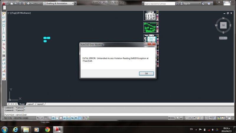
some persons sent me CAD files , when i tried to open them , at once AutoCAD crashed and an error message appeared ... Autocad 2012 is there a way to check if the CAD file contains virus or not ?? - Repairing didn't work !! , only unistalling solved the problem , but when tried to open the file again , the program crashed

-

Defun Function calls with arguments, please help!!
duanuys posted a topic in AutoLISP, Visual LISP & DCL
Here is my section of code that I need help on. The error VisualLISP is giving me is :Function Canceled. The builder doesn't complain, so my syntax is correct, but its just not working. I am making simple lines and changing the color to them using the "change" command with a function call. Can anyone please tell me what I am doing wrong?? Also just fyi in defun c:wellplace.. i just used the line (color po2) because i don't want to post the whole code in, everything else works fine, but breaks when it gets to that line. (defun color (col) (command "change" col "" "P" "C" "T" "255,0,0" "") ) (defun c:wellplace () (color po2) ;po2 is a "point number 2" that is calculated else in the code. ) Shouldn't it take the po2 which is a polar point, consisting of x,y,z coordinates and pass it along to the "color function"? I am doing this, because I need to do the "change" command a good 8 times, and i don't want 8 of duplicate lines of the same thing. Also if i go with not defining a function and just inputting the "change" command right into the body of my code, it works perfect, and replace 'col' with 'po2' so what gives? -
I need help extruding this. my teacher hasn't really gone over AutoCAD 3D much so bear with me. Im a junior in high school btw What i need to do is get everything extruded to look like a gate. for the curvy things i used the command join to make all the lines of them go together. i did this to 1 and then copied that 1 to make all the others. the outer lines are joined too. basically rectangles. when i extrude it looks like a pink solid. you cant see any of the detail. it just looks lipe a pink brick help?
-

Problem Converting Surface Model to Solid Model
ADRowe posted a topic in AutoCAD 3D Modelling & Rendering
Hey All, I am working on a 3D model of a pool floor for a project that to be supported by walls. I have just started to use surface modelling and I thought I would give it a go using it, when I have gone to convert it to a 3D solid using the sculpt tool I get the error message "Modeling Operation Error: Operation did not add or remove material. Solid creation failed, no watertight volume detected." I am well a wear of what this means but I can't find the gap/hole anywhere. If you could help me out in locating them it would be much appreciated, also any tips and trick to surface modelling would be also appreciated. 3D model is attached. Pool Floor2.dwg -
I need to update the tag, prompt, value tab in the current block attribute. I can change the tag and the value tab but not the prompt. Any help will be appreciated. The approach am taking is; AcDbDatabase *dwgDb; AcDbBlockTable *pBlockTbl; AcDbBlockTableRecord *pModelSpaceTblRcd; AcDbBlockTableRecordIterator *pModelSpaceItr; AcDbEntity *pEntity; AcDbBlockReference *pBlockRef; AcDbAttribute *pAttribute; AcDbObjectIterator *pAttrItr; AcDbObject *pObject; TCHAR tagBuffer[sINGLE_LINE_INPUT_LENGTH_SHORT]; // Prepare attribute location measurements AcDbObjectId idOfEntity; dwgDb = NULL; dwgDb = acdbHostApplicationServices()->workingDatabase(); if (dwgDb == NULL) { AfxMessageBox(_T("Internal Error !")); return false; } dwgDb->getSymbolTable(pBlockTbl, AcDb::kForWrite); pBlockTbl->getAt(ACDB_MODEL_SPACE, pModelSpaceTblRcd, AcDb::kForWrite); pBlockTbl->close(); // Get an iterator to that we can iterate / pinpoint // the desired entity via the objectID pModelSpaceTblRcd->newIterator(pModelSpaceItr); // Go to the block reference / objectID if(pModelSpaceItr->seek(thePANBLKBlockId) != Acad::eOk) { AfxMessageBox(_T("Internal Error !")); delete pModelSpaceItr; pModelSpaceTblRcd->close(); return false; } // Access the block reference pModelSpaceItr->getEntity(pEntity, AcDb::kForWrite); pBlockRef = AcDbBlockReference::cast(pEntity); // Prepare iterator to move through block's attributes pAttrItr = pBlockRef->attributeIterator(); for(pAttrItr->start(); !pAttrItr->done(); pAttrItr->step()) { acdbOpenAcDbObject(pObject, pAttrItr->objectId(), AcDb::kForWrite); pAttribute = AcDbAttribute::cast(pObject); _tcscpy_s(tagBuffer, SINGLE_LINE_INPUT_LENGTH_SHORT, pAttribute->tag()); pAttribute->upgradeOpen(); // LEFTBFHGT if(_tcscmp(tagBuffer, _T("LEFTBFHGT")) == 0 || _tcscmp(tagBuffer, _T("LEFTHEIGHT")) == 0 ) { TCHAR attrText[COMMENT_LENGTH_SHORT]; _tcscpy_s(attrText, COMMENT_LENGTH_SHORT, pAttribute->textString() ); AcDbAttributeDefinition *tempAttrDefinition = new AcDbAttributeDefinition(); tempAttrDefinition->setPosition(pAttribute->position() ); tempAttrDefinition->setTag(_T("LEFTFFHGHT")); tempAttrDefinition->setPrompt(_T("Left Front Face Height.")); tempAttrDefinition->setTextStyle(idTextStyleLeroy); tempAttrDefinition->setHeight(.32); tempAttrDefinition->setRotation(0); pAttribute->setAttributeFromBlock(tempAttrDefinition, pBlockRef->blockTransform() ); pAttribute->transformBy(pBlockRef->blockTransform() ); pAttribute->downgradeOpen(); pModelSpaceTblRcd->appendAcDbEntity(pEntity); pBlockTbl->upgradeOpen(); pModelSpaceTblRcd->upgradeOpen(); tempAttrDefinition->close(); } pAttribute->close(); } // Free the attribute iterator delete pAttrItr; pBlockRef->close(); delete pModelSpaceItr; pModelSpaceTblRcd->close();
-
Hi there .. This lisp helps you to quick draw pile section and profile with annotation text around entities. Just drag & Drop. Command : "PILE" Please feedback )Pile.lsp
-
Hi, I need to change colors on a dwg file and to see them changed on Navis. Let me explain : - I'm gonna receive .dwg every weeks, same name but updated (ex : 1.dwg, 2.dwg, 3.dwg) - I'm planning to xref all the .dwg on the same drawing to change the colors I need (with Visretain : 1, I'm gonna keep the modified color) (Xref.dwg) My problem is when I append Xref.dwg, it takes the colors from the originals files (1.dwg, 2.dwg, 3.dwg). Does any of you know how to do it? Thank you Ildan
-
Hi all. I'm sure that this question has probably been raised countless times over; I can't find any solution, so please accept my apologies in advance. I have AutoCAD at work and on my desktop at home, but only True View and Design Review on my laptop. I need to work from my laptop and need to view acad dwgs; that's it, but I need the external references (xrefs) loaded within dwgs too. Other than etransmitting etc is there a way/program to simply open an acad dwg and be able to see it? Even as an uneditable entity/image or something? I just need to see it - from the .dwg file itself; no PDF or anything like that. Thanks! Michael
-
Hi all! Having a bit of trouble with something I thought would be basic in CAD! I'm going to do some freelance visualisation work and the architects have supplied me with plans (PDF and DWG), some elevations are at a scale 1:200@A1 others are 1:100/1:75/1:50 etc. How do I convert or scale these drawings back to true size 1:1 so I can take the splines over to 3DS Max to speedup my workflow? Am I missing something simple here? I tried selecting and scaling up by x50/x75/x100 etc but nothing matches up with the dimensions given! Fairly advanced with the workflows of Max and Maya as an animation graduate but new to AutoCAD! Any help would be immensely appreciated!!! Kind regards, Andy
-
Dear AutoCAD gurus, I am having a serious problem with scaling in my current project. I am using AutoCAD 2014 Civil 3D. All of my viewports are set to 1"=40', but when I print them out, they are consistently off by 1/40th of an inch. It should be noted that I first print them into pdfs, but I am having this problem no matter if I print from the pdf or if I print them from autocad directly. Has anyone else faced a similar issue? Thank you.
-

AutoCAD scaling problem
sss8885 posted a topic in AutoCAD 2D Drafting, Object Properties & Interface
Dear AutoCAD gurus, I am having a serious problem with scaling in my current project. I am using AutoCAD 2014 Civil 3D. All of my viewports are set to 1"=40', but when I print them out, they are consistently off by 1/40th of an inch. It should be noted that I first print them into pdfs, but I am having this problem no matter if I print from the pdf or if I print them from autocad directly. Has anyone else faced a similar issue? Thank you. -
Dear AutoCAD gurus, I am having a serious problem with scaling in my current project. I am using AutoCAD 2014 Civil 3D. All of my viewports are set to 1"=40', but when I print them out, they are consistently off by 1/40th of an inch. It should be noted that I first print them into pdfs, but I am having this problem no matter if I print from the pdf or if I print them from autocad directly. Has anyone else faced a similar issue? Thank you.
-
Hello everyone - been a long time since I was on here I've created a solid model using Autocad 2014 which has multiple solid entities that I want to export to Revit 2014 as individual entities. When I import it into Revit 2014 however the drawing comes in as a single item, and if I right click the bounding box and try to either partial or full explode it, it completely disappears. Is there any way of getting the entities changed from Autocad to Revit so I can add BIM information to each separate entity within Revit? Thanks in advance for any advice and a big "Hello" to anyone that remembers me Spacepig
-
I'm writing a program to import a WMF into the AutoCad Drawing. I haven't been able to find any reference for the import command, so I can't figure out why it's not working. According to Visual Studio, the Import command needs these things to work. Import(String FileName, Object InsertionPoint, Double ScaleFactor) Simplified Code: Imports Autodesk.AutoCAD.Runtime Imports Autodesk.AutoCAD.ApplicationServices Imports Autodesk.AutoCAD.DatabaseServices Imports Autodesk.AutoCAD.Geometry Imports Autodesk.AutoCAD.EditorInput Imports Autodesk.AutoCAD.Interop Dim AcadApp As Autodesk.AutoCAD.Interop.AcadApplication AcadApp = CType(GetObject(, "AutoCAD.Application.18.2"), Autodesk.AutoCAD.Interop.AcadApplication) acadDoc = AcadApp.ActiveDocument acadDoc.Import("C:\Users\C\Documents\Drawing1.wmf", New Point3d(2, 2, 0), 2.0) When I comment out the last line of code, acadDoc.Import("C:\Users\C\Documents\Drawing1.wmf", New Point3d(2, 2, 0), 2.0) It runs fine. The error I'm getting is when I run it AutoCAD, ************** Exception Text ************** System.ArgumentException: Value does not fall within the expected range. at System.StubHelpers.ObjectMarshaler.ConvertToNative(Object objSrc, IntPtr pDstVariant) at Autodesk.AutoCAD.Interop.IAcadDocument.Import(String FileName, Object InsertionPoint, Double ScaleFactor) at TestSelectingFiltering.TestSelecting.MyCommands.FilterBlueCircleOnLayer0() at Autodesk.AutoCAD.Runtime.CommandClass.InvokeWorker(MethodInfo mi, Object commandObject, Boolean bLispFunction) at Autodesk.AutoCAD.Runtime.CommandClass.InvokeWorkerWithExceptionFilter(MethodInfo mi, Object commandObject, Boolean bLispFunction) at Autodesk.AutoCAD.Runtime.PerDocumentCommandClass.Invoke(MethodInfo mi, Boolean bLispFunction) at Autodesk.AutoCAD.Runtime.CommandClass.CommandThunk.Invoke() Any help would be greatly appreciated, Thanks!
-
We have aAutoCad file with MagiCad object inside, we need modify some text from manyMAGIDIMLINE, for that we use MagiCad Object Enabler and explode it. But theresulting block contains different information from the original. For example,we have a MAGIDIMLINE with “VG + 16.32” or “VG + 16.30” ,text inside, and whenwe explode it, the resulting blocks have “VG +-0.18” and “VG +-0.20”, we don’tknow what happen!. We haveaccess to the original projects, but only need to modify one file for survey. Any Idea??? Thanks!!!
-
Hi, I am trying to create a macro (or lisp) and am struggling to find how I would do it. Basically what I want to achieve is this: Click Custom button, Click first point (p1) Click second point (p2) Insert block at p1 and set scale to equal distance between p1 and p2 Set bearing to the bearing between p1 and p2 then end. The process will take 3 clicks including click the custom button. This is to basically speed up inserting doors. I was thinking possible making it draw a line when you click p1 and p2 then use this line to grab the start of line, end of line and bearing. Or using variables. Any help would be appreciated, or pointing in the right direction. I don't expect anyone to do all the work for me, just a hint would be awesome.
-

Import real time gps coordinates from Leica CS10 to Autocad
cmscardoso posted a topic in AutoCAD General
Hello. Is it possible to import real time gps coordinates from Leica CS10 to Autocad? Is it a function in Autocad or will i need a third part software to accomplish that? Thanks for your help -
Alright so I have to subtract that little box inside the guide block so it looks like this http://gyazo.com/bc7fdf0552af580344d665e45127b2db I have no idea how to do this.. Thanks:? exploded version guideblock.dwg
-

LSP file It is Not Working Some thing is missing
sam_rcr posted a topic in AutoLISP, Visual LISP & DCL
Dear Friends , Please Help Me out With This LSP file IT is Not Working, Some thing is missing in this, i am attacheing my lsp file for ur refrence.... its asking output file. i dont have that file -
I have a LISP that creates balloons simply for me, the problem is the LISP only makes balloons with a dot on the end. I have been playing about with it trying to make it have the option to put an arrow head on the end but can't work it out after trying for quite a while. The draughtsmen here have been using it since they started so I'm not sure if LISPs will be written the same way now as they were in '87! Any help would be great. Cheers. Here is the code; ;---------- BALLOON.LSP Simon Jones 24-8-87 ; Macro to simplify the construction of item-number labels. ; The size of the dot, text and balloon are based on the dimensioning ; variables. If DIMASZ is set to zero the dot is not drawn. If the ; current text style has a fixed height then that height is used to ; scale the balloon and its text. ; A null response to the first prompt ("From point: ") will terminate ; the command. ; Numeric text is incremented to aid itemising components of a drawing (defun C:BALLOON (/ a b c d h l r txt) ; a : Leader start ; b : Balloon centre ; c : Leader end point ; d : Dot diameter ; h : Text height ; r : Balloon radius ; Store and set system variables (setq ce (getvar "CMDECHO")) (setq bm (getvar "BLIPMODE")) (setvar "CMDECHO" 0) (setvar "BLIPMODE" 0) ; Set dot diameter to tenth of arrow head size (setq d (* (getvar "DIMSCALE") (getvar "DIMASZ") 0.3)) ; Check whether the current text style has a fixed height (setq ts (cdr (assoc 40 (tblsearch "STYLE" (getvar "TEXTSTYLE"))))) (if (zerop ts) ; Set balloon radius based on dimension text height (setq r (* (getvar "DIMSCALE") (getvar "DIMTXT") 1.85) h (* (getvar "DIMSCALE") (getvar "DIMTXT") 1.3) ) ; Set balloon radius based on current style text height (setq r (* ts 1.85)) ) ; Get start point (a null response will terminate function) (setq a (getpoint "\nFrom point: ")) (if a (progn ; Get balloon cntre disallowing null responses (initget 1) (setq b (getpoint a "\nBalloon centre: ")) (if (null oldtxt) (setq oldtxt "1")) (prompt (strcat "\nText <" oldtxt ">: ")) (setq txt (getstring)) (if (= txt "") (setq txt oldtxt)) (setvar "BLIPMODE" 0) ; Draw dot if DIMASZ is set (if (> d 0) (command "DONUT" "0" d a "")) ; Calculate point where leader crosses balloon (setq c (polar a (angle a b) (- (distance a b) r) ) ) ; Draw leader (command "LINE" a c "") ; Draw balloon (command "CIRCLE" b r) ; Draw text (checking against fixed text height) (if (zerop ts) (command "TEXT" "M" b h "0" txt) (command "TEXT" "M" b "0" txt) ) (setq oldtxt (itoa (1+ (atoi txt)))) ) ) ; Reset system variables (setvar "BLIPMODE" bm) (setvar "CMDECHO" ce) (princ) )