Search the Community
Showing results for tags 'dimension'.
-

Continuous Running Dimensions, is it possible?
e_anders3 posted a topic in AutoCAD 2D Drafting, Object Properties & Interface
Is there a way to create a continuous dimension line that uses running dimensions instead individual segments? I know that you can do baseline measurement but I received a request to have the dimensions look like a continuous dimension line, but be running dimensions. I'm aware of UCS -> cordinate -> baseline (dimension) That's pretty much what I want but I want it to be a line with arrows and what not. I'm not even sure if it's possible. I've attached an image of what I'm looking for if it helps. Thanks!
-
Hello evreryone, I am new Here. Also new in Autocad. I have to change dimension of 100s of 3d table top in dwg format. like, now the dimension is 1 inch. I have to make it 1.5 inch. I am wondering if there are any tools or script to do that. Thanks in advance. Best Regards Meraj
-
I am experiencing some difficulties when positioning ifeatures. This happens to the ifeatures I have created as well as those provided with Inventor. I place the feature on the plane ok, and I select 'Open sketch' in the dialog box. All ok so far. I place the first dimension to position the ifeature and enter either a numeric value or enter a parameter. When I press return or click the green tick button on the dimension, I seem to leave the sketch mode, and return to the part. However, it seems that Inventor is not fully out of sketch/dimension mode because I have to right click to select Esc or Ok before I can then right click on the sketch to edit it and add more dimensions to position the ifeature. So basically I can only add one dimension to the ifeature at a time. I then have to re-enter the sketch to add another single dimension. Any ideas as to what I'm doing wrong, or what settings I could investigate. Using Inventor Professional 2013
-
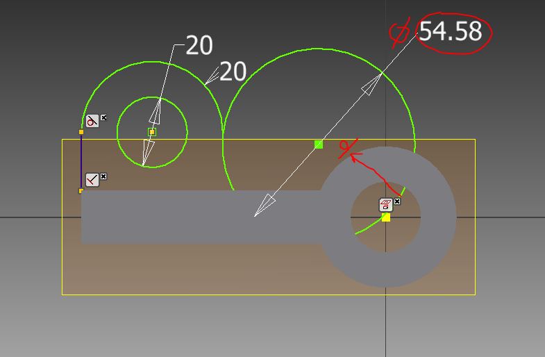
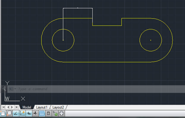
I am modeling this part in inventor and don't know the dim that was mark in red? the dia of the two circles were given and 50mm from one end was also given but the total length of the obj was not given. Does anyone know what is the unknown dim in red?. By ignore one unknown dim and continue working. how can i make one of the circle tangent smoothly but not going in the hole as it shown on red arrow on the image? (Note: Dia has to be 54.58 mm (27.29x2). please advice if there is other alternate method the model this part. Thank.
-
A couple of queries about being fully constrained: Consider the attached part. Edit Sketch 1. Display all Constraints. What two dimensions are missing? Change Horizontal Dimension (vertical axis to arc centre) to 150. This distorts the arcs on my Inventor 2015. Why is this? Thanks Underconstrained_Part.ipt
-
Has anyone seen a dimension lisp where I could replace the text with, for example, "? /P E.O.S." automatically without having to manually do it? I have other things to use this with but if someone where to provide something like this I think I could manipulate it to what I want. Ideally, I'd like to be able to copy a dimstyle that I already have and just have a constant in place of the actual dim. This way it would keep my layers, arrow types and other settings, etc... Any ideas are appreciated! -Nobull
-

Connect variables to dimension value
slavasp posted a topic in AutoCAD 2D Drafting, Object Properties & Interface
Hello all, I added in AutoCad 2006 two variables. Firstly, constant "$Dim1= 3000" Secondary, function "ddd=$Dim1-100" How I can connect line geometry dimension value to function? Is mean when I change constant automatically update line geometry dimension value. Best Regards Stanislav Spektor Mechanical Engineer -

Add bend to leader lines
david1-b posted a topic in AutoCAD 2D Drafting, Object Properties & Interface
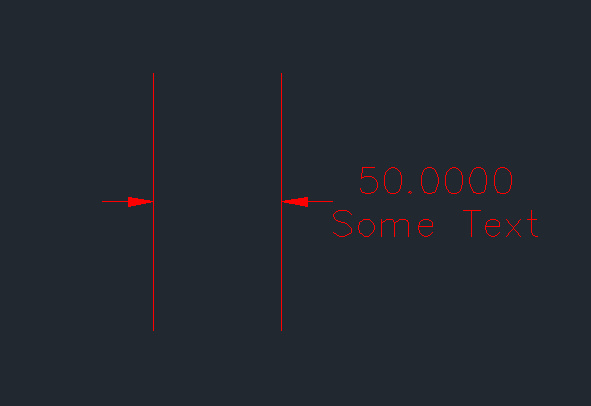
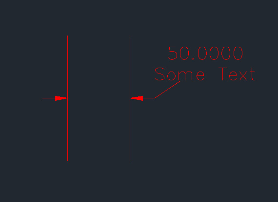
Hello, I am trying to add a bend to my leader lines using Civil 2013. I have attached two images the first one is of my standard leader (dimension is inline with the leader line), the second one is a leader I "faked" to illustrate my desired leader style, a perpendicular leader then a bend to some text. Does anyone know how a leader like this can be made. In this example I am using a dimension, but I would be happy with a solution that used multileader. Thanks If any clarification is required please ask
-

Help, get value Attributes Block and Dimensions to Excel
minhphuong_humg posted a topic in AutoLISP, Visual LISP & DCL
Hi all, I have a drawing with Attributes and Dimension. I want get value Attributes and Dimensions to Excel (2010) (view file Now.rar attachment). Please, help me get value Attributes and Dimensions to Excel by autolisp. Thank you very much! File: Now.zip -
Would someone be able to create a dimension lisp that: Instead of numerical dimension, only shows a "?" And also puts a rev cloud around it as well I see when creating a new dimstyle, you can draw a frame around it. Didn't know if you could change that to a cloud automatically? I also need to be able to change the dimstyle its on as when we cloud different types of areas, they may need to be on a different layer. It can get tedious when dimensions are not given and I have to change each one to "? D.E." or "? E.O.S." I've searched around for something like this but couldn't really find anything. Any help from the gurus here are appreciated as always. Thanks, Nobull
-

Displaying variables and characters in an entmake dimension
plackowski posted a topic in AutoLISP, Visual LISP & DCL
Hello! I just stared working in AutoLISP a few days ago, and I've come across a problem. I need to create a dimension line where the dimension value is dependent on an input value. So if the input is y, then the text on the dimension line should equal 4.5*(y+1) inches, and it also needs to have a character width of 0.75. Currently, it just displays 4 1/2". As I understand it, this would be a real number, meaning I can't concatenate it with the inches symbol. Any help would be greatly appreciated! (defun c:retan (/ p1 p2 p3 p4 x y i j)(setvar "osmode" 0) (setq p1 (getpoint "\nfirst corner of rectangle: ")) (setq x (getint "\nEnter Horizontal Count: ")) (setq y (getint "\nEnter Vertical Count: ")) (setq p3 (list (+ (+ 1.625 (* 0.8125 (- x 1))) (car p1))(+ (+ 1.625 (* 0.8125 (- y 1))) (cadr p1)))) (setq p2 (list (car p1)(cadr p3))) (setq p4 (list (car p3)(cadr p1))) (command "pline" p1 p2 p3 p4 "c") ;c closes the rectangle's fourth side (entmakex (list (cons 0 "DIMENSION") (cons 100 "AcDbEntity") (cons 8 "E-DIMS") ;; 8 Layer (cons 100 "AcDbDimension") (cons 10 (list (- (car P1) 0.7) (cadr P2) 0)) ;; 10 Arrow Node (cons 11 (list (- (car P1) 0.9) (/ (+ (cadr P2)(cadr P1)) 2) 0)) ;; 11 Text Position (cons 70 160) (cons 1 "{\\W0.75;4 1/2\"}") ;; 1 Contents of Dimension Textbox (cons 71 5) ;; 71 Text Alignment (5=centered) (cons 42 0.8125) (cons 53 1.5708) ;; 53 Text Rotation (cons 3 "REW-1_.125txt") (cons 100 "AcDbAlignedDimension") (cons 13 P1) ;; 13 point on line (cons 14 P2) ;; 14 point on line (cons 50 1.5708) ;; 50 Angle (radians) 1.5708 (cons 100 "AcDbRotatedDimension"))) (setvar "osmode" 16383)(princ) ) -
Does anyone know of a number keypad available with feet and inches keys?? I unfortunately cannot download any software of any kind at work and cannot use programmable keyboards. (I can't even setup my extra buttons on my USB mouse) I've found them tab and escape buttons which I would also like. But entering dimensions most of the day, this would be helpful! Thanks, Nobull
-
 I have two viewports, one that is not rotated at 1:50 scale, the other rotated at 1:20 scale, and using associative dimensioning, therefore viewing the same model object with two associative scales. The rotated viewport is showing the dimenions upsidedown since it is rotated more than 180deg. If I modify the dimension properties to Left to Right instead of Right to Left, it rotates my other unmodified viewport. The only way right now to have the dimensions showing properly, is to print the first pages with the unmodified viewports, then modify the dimension properties, and then print the rotated viewport pages. It there any way around this? Thanks.
 -
I just want to know the steps how to do this (referred to attached file). I got dizzy :ouch:
-

can anyone please change this dimension lisp?
Nobull84 posted a topic in AutoLISP, Visual LISP & DCL
I have a lisp, from Kent Cooper circa 2010, that enters a dimension at each line that intersects. It seems to be limited as to what kind of objects it breaks at. The CAD at my company has custom objects they have incorporated and the lisp does not recognize them as objects. Anyone able to change this around a little to dimension ALL objects? Thank you. ;; QuickDimAligned.lsp [command name: QDA] ;; To make a collinear series of Aligned Dimensions along ;; a single fence line, between all intersections of that line ;; with intersectable objects. ;; Kent Cooper, July 2010 ;;;; [optional features could be added: account for other ;;;; Coordinate Systems; set layer and/or dimension style] (defun C:QDA (/ *error* orth osm blipm dse1 dse2 pt1 pt2 ss obj intp intc inclist intpt distpt distpts intclist intplist) (defun *error* (errmsg) (if (not (wcmatch errmsg "Function cancelled,quit / exit abort")) (princ (strcat "\nError: " errmsg)) ); end if (command) (setvar 'osmode osm) (setvar 'orthomode orth) (setvar 'blipmode blipm) (setvar 'dimse1 dse1) (setvar 'dimse2 dse2) (command "_.undo" "_end") (setvar 'cmdecho cmde) ); end defun - *error* (vl-load-com) (setq cmde (getvar 'cmdecho)) (setvar 'cmdecho 0) (command "_.undo" "_begin") (setq orth (getvar 'orthomode) osm (getvar 'osmode) blipm (getvar 'blipmode) dse1 (getvar 'dimse1) dse2 (getvar 'dimse2) ); end setq (setvar 'orthomode 0) (setq pt1 (getpoint "\nStarting Point of QuickDim virtual line: ") pt2 (getpoint pt1 "\nOther End: ") ss (ssget "F" (list pt1 pt2) '((0 . "*LINE,ARC,CIRCLE,ELLIPSE,RAY,SOLID,3DFACE,REGION"))) ); end setq (setvar 'osmode 0) (setvar 'blipmode 0) (setvar 'dimse1 1) (setvar 'dimse2 1) (command "_.line" pt1 pt2 "") (setq templine (entlast)) (repeat (sslength ss); for each object in selection (setq obj (vlax-ename->vla-object (ssname ss 0)) intline (vlax-ename->vla-object templine) intp (vla-intersectwith obj intline acExtendNone); INTersection Point(s) intc (safearray-value (variant-value intp)); INTersection Coord's [all together] intclist (append intclist intc); cumulative list for all objects so far ); end setq (ssdel (ssname ss 0) ss); remove object ); end repeat (entdel templine) (repeat (/ (length intclist) 3); number of [apparent] intersections (setq intpt (list (car intclist) (cadr intclist) (caddr intclist)); first remaining point distpt (cons (distance pt1 intpt) intpt); list: distance followed by point coordinates distpts (cons distpt distpts); list of those lists intclist (cdddr intclist); remove first point's coordinates for next one ); end setq ); end repeat (setq intplist ; list of intersections in order of distance from pt1 (mapcar 'cdr ; strip distances off sorted list (vl-sort distpts '(lambda (p1 p2) (< (car p1) (car p2))); sorted by distance [first element] ); end sort ); end mapcar ); end setq (command "_.dimaligned" (car intplist) (cadr intplist) (cadr intplist)) (setq intplist (cddr intplist)); remove first two points [already used] (while intplist ; as long as there's still another point (command "_.dimcontinue" (car intplist) "" "") (setq intplist (cdr intplist)) ); end while (setvar 'osmode osm) (setvar "orthomode" orth) (setvar 'blipmode blipm) (setvar 'dimse1 dse1) (setvar 'dimse2 dse2) (command "_.undo" "_end") (setvar 'cmdecho cmde) (princ) ); end defun - QDA (prompt "\nType QDA for QuickDimAligned collinear intersection dimensions.") (princ) -

Cannot rotate dimension text to desired angle
jdavid10 posted a topic in AutoCAD 2D Drafting, Object Properties & Interface
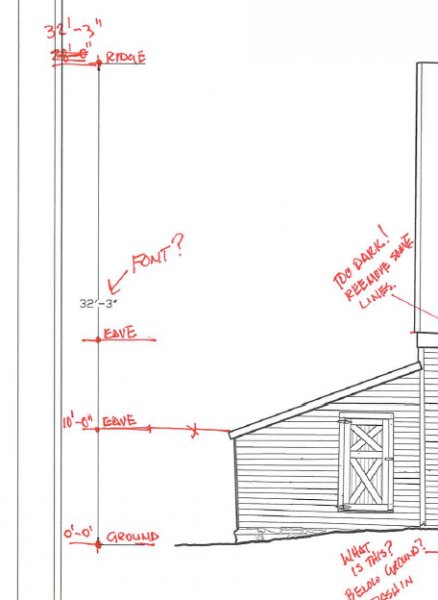
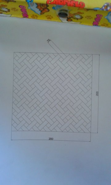
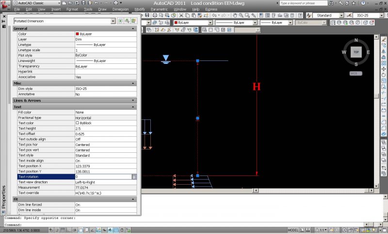
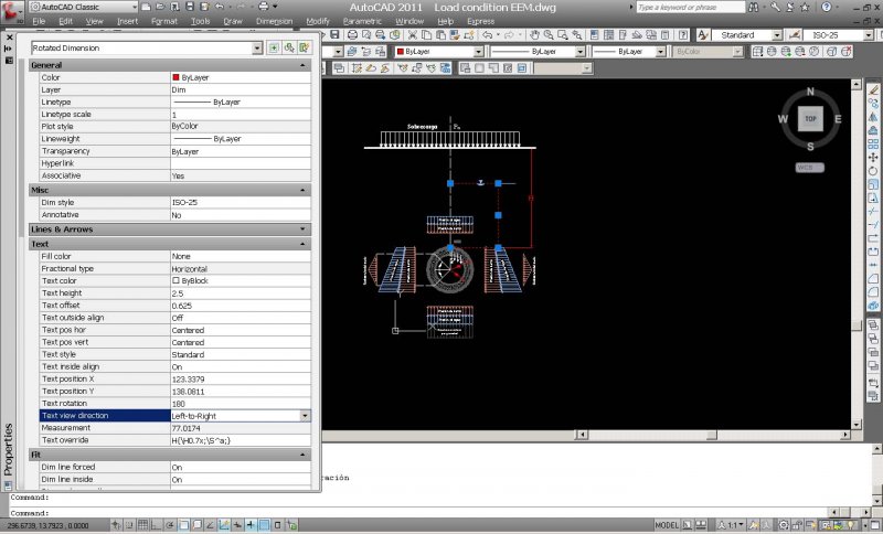
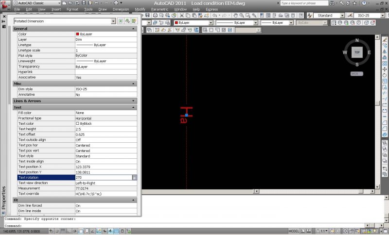
Hello everyone, I'm making this diagram of the load condition acting on tunnels to explain a Japanese set of equations that are used for the structural analysis for tunnels: But, there is one problem I have. I'm trying to set up the text for the dimension between the water table and the tunnel "Ha" to look horizontal. However, if I click on the properties box and write 90 in the rotation box right next to where it says "text rotation," the dimension text does not rotate 90 degrees; if instead I try to rotate it 180° then it only rotates 90° (and in the opposite direction) instead of 180°. It doesn't matter how many degrees I choose, it won't rotate my dimension "Ha" to desired angle to make it look horizontal. OK I know it's hard to explain my problem with just writing, so I've posted a few pictures: In this one, the dimension is at 0°; I've only opened the properties box to attempt and rotate it: Now I write 90 in properties box but the dimension text does not rotate at all; it remains at 0 as it is shown in the following image: Next I try to rotate 180, just to see what happens; and it does rotate (only 90 degrees!): I finally try to rotate the text 270 just to see if it rotates to desired angle and it does rotate (180 degrees from original position). As shown below: It doesn't matter how many degrees I choose, I cannot make it look horizontal. Is AutoCAD wrong? Or am I wrong? lol xD Any ideas? I'm about to loose a quarter pound of my hair from just thinking about this. Lol just kidding but this is very annoying. How can I set up my dimension text "Ha" to look horizontal? Please help.
-

How do I control display of dimensions?
Vagulus posted a topic in AutoCAD 2D Drafting, Object Properties & Interface
Having drawn this spacer for the tutorial I am following, I decided to add the dimensions. The dimension shown here is 200mm but you wouldn't know that. How do I set the dimensions so I can see the arrowheads and read the text?
-
In looking for a lisp routine that performs the sum selected dimensions, found one that I believe to be ideal for my work. Could the author or another member of the forum to make a change? It would be ideal for me to make the sum property>%). TextOverride>% Rotated Dimension object. I tried to make the change but as I am not aware that language still did not succeed. Returns the error "misplaced dot on input". Below the original routine. Dims2Field.lsp (defun c:Dims2Field ( / *error* spc doc pt uFlag ss ids ) (vl-load-com) ;; © Lee Mac 2010 (defun *error* ( msg ) (and uFlag (vla-EndUndomark doc)) (or (wcmatch (strcase msg) "*BREAK,*CANCEL*,*EXIT*") (princ (strcat "\n** Error: " msg " **"))) (princ) ) (setq spc (if (or (eq AcModelSpace (vla-get-ActiveSpace (setq doc (vla-get-ActiveDocument (vlax-get-acad-object) ) ) ) ) (eq :vlax-true (vla-get-MSpace doc)) ) (vla-get-ModelSpace doc) (vla-get-PaperSpace doc) ) ) (if (and (ssget '((0 . "*DIMENSION"))) (setq pt (getpoint "\nPick Point for Field: "))) (progn (setq uFlag (not (vla-StartUndoMark doc))) (vlax-for obj (setq ss (vla-get-ActiveSelectionSet doc)) (setq Ids (cons (GetObjectID obj doc) Ids) ) ) (vla-delete ss) (vla-AddMText spc (vlax-3D-point pt) 0. (if (= 1 (length Ids)) (strcat "%<\\AcObjProp Object(%<\\_ObjId " (car Ids) ">%).Measurement \\f \"%lu6\">%") (strcat "%<\\AcExpr" (lst->str Ids " %<\\AcObjProp Object(%<\\_ObjId " ">%).Measurement >% +") ">%).Measurement >% \\f \"%lu6\">%" ) ) ) (setq uFlag (vla-EndUndomark doc)) ) ) (princ) ) (defun lst->str ( lst d1 d2 ) ;; © Lee Mac 2010 (if (cdr lst) (strcat d1 (car lst) d2 (lst->str (cdr lst) d1 d2)) (strcat d1 (car lst)) ) ) (defun GetObjectID ( obj doc ) ;; © Lee Mac 2010 (if (eq "X64" (strcase (getenv "PROCESSOR_ARCHITECTURE") ) ) (vlax-invoke-method (vla-get-Utility doc) 'GetObjectIdString obj :vlax-false ) (itoa (vla-get-Objectid obj)) ) ) Thank in advanced. Luis Augusto.
-
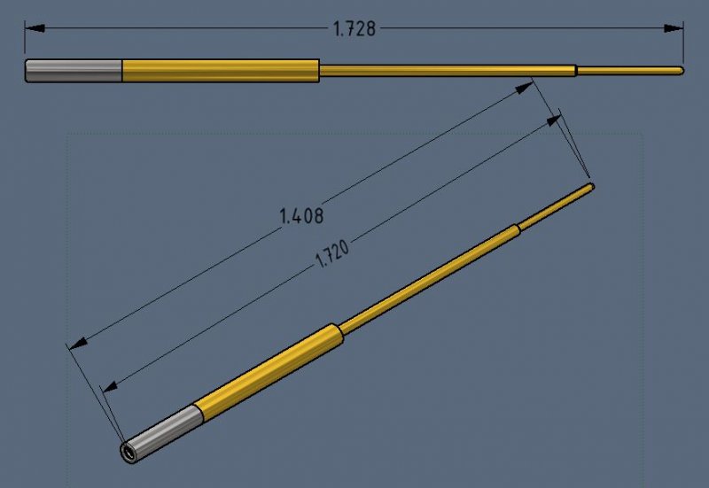
I have been racking my brain as to how to make this work and am at a loss so please help me figure this out. I have a simple assembly of a pin and hood. The pin has a spherical end and the hood has a fillet edge that continues to wrap spherically inward. When trying to dimension the OAL on the side view it is easy and obvious. When trying to do it on the iso view the measurements are never correct. I do not have a good point to choose from on the hood as it has a fillet edge not a square point, which would be easy. Without a flat surface to go off of and in the paper space there is no way to specify quadrants/edges/planes when annotating. The space bar trick helps but does still does not dimension to the right point. When I try to use the RETRIEVE DIMENSIONS action, I can get the OAL of the pin and OAL of the hood separately, but not as an assembly OAL. I tried to go into the assembly and create random sketches, planes, fake dimensions that might be used by the retrieve dim action, but to no avail. This is the simplest part I am using as a reference, I have much more elaborate parts that are giving me the same issue. It would seem straightforward, but for the life of me cannot find an easy way to get that simple OAL. Thanks for the help. Go Sun Devils!
-

Unable to view items as i draw
cbgcm posted a topic in AutoCAD 2D Drafting, Object Properties & Interface
For some strange reason when I got to work this morning I was unable to view items as I draw. I can see lines as I draw once I specify the first point with ortho on or off, but I can't see shapes (dimensions, circles, rectangles, ellipse, or box) while I draw. Once I select the second point the object does appear but a setting has changed and I can't figure out how to get it back to normal. Any help would be greatly appreciated. -
Hello! I was wondering how I would go about writing a function that would calculate the length of a diagonal of a rectangle using SQRT function? I've been trying but so far nothing! Thanks!
-
is there a function in autocad that can display the coordinates of a point...like when we use linear dimension lengthe of line is displayed..
-

Automate dimensioning process?
Meecad posted a topic in AutoCAD 2D Drafting, Object Properties & Interface
I work in plumbing design and am constantly burdened by the tedious task of setting out hundreds upon thousands of penetrations every month for the guys on site to locate their plumbing points through the slab. They use a GPS system to expedite the plotting, but first I provide a CAD file with just 3 layers; GRids ( a line ), Wastepoint ( a donut poly line ) and Fixture Name ( multi text) which the survey program can interpret and set out from ( actually, the surveyor only needs one point, which he grabs from the site grids that I provide ). So that's all good, but on top of this I must dimension off the grids every point so that measurements can be done on site as back-up/cross checking. Of course I can't have dims overlapping each other. Is there any way to automate this part of the process? Taking a dim from the nearest grid (x and y axis) to the centre of the object I use for the penetration. -

Vertical dimension text gets bolder than all other text when scaled down!
ItsChrisRay posted a topic in AutoCAD 2D Drafting, Object Properties & Interface
We've been fighting with this and the conclusion we've come to is that it's an autocad problem and there's nothing we can do about it. We have detail drawings that contain horizontal and vertical dimensions. They're drawn at full scale in model space and saved as individual drawings. We then insert them as blocks onto a sheet in paper space, scaling them down to 1/2", 1/4" scale ETC. Here's the problem - all the vertical dimension text appears bolder than everything else when scaled down. Horizontal text is just fine, diagonal text also looks a little bolder though. It seems that it's just a quirk of autocad that it does that. -

Making Metric Annotation Scale Not Working
chitownCADteacher posted a topic in AutoCAD 2D Drafting, Object Properties & Interface
Hi All, I created a new annotation scale to convert mm to inches and changed my DIMSTYLE to dimension to annotative as well, but when I go to dimension nothing happens. My dimensions, arrows and extension lines are still small. What's more bizzare is when I click the dimension and right click properties, it says my annotation scale is 1:1 and it's not set to change to annotative even though my DIMSTYLE says to. So I have to manually click the dimensions and change them all to my DIMSTYLE and change the annotation scale. What did I do wrong when I created the new annotation scale?!?!