Search the Community
Showing results for tags 'surface'.
-

Need Assistance getting distance from surveyed point to a surface
zabron05 posted a topic in Civil 3D & LDD
Hello, If you are looking at plan view, I have a bunch of points surveyed for blastholes: x x x x x x x x x x x x x x x x These points all vary in height. I have a surface created under hole collars representing the chemical contact between two different rock units. I'm trying to project a line from the collar of the blast hole, vertically down, to intersect with the surface and determine that length so I can inform the drillers what depth the holes need to be drilled to. Currently, here's my workflow to get the required depths: Survey the blast hole locations prior to drilling. Come back to the office, import my points from the survey to CAD. Determine the extents of the blast. Extend the existing geologic model to determine the hypothetical depths. The drillers then drill sample holes to determine the depth of the surface and the surface is updated within two days. I then need to go back out to the blast holes and use my survey equipment to stakeout the DTM. I then go back around to the holes and record on scratch paper the depths to the DTM. I then come back to the office and annotate the drawing with the required depths. I then finally plot the drill instructions for the blasthole drills. I appreciate any and all help!! -

Help! 3D model not watertight / converting surface to solid / terrain modeling
zjkaufman posted a topic in AutoCAD 3D Modelling & Rendering
Hi all, I am having urgent trouble with a project involving 3d modeling of terrain. This is a graduate-level project requiring ArcMap and Star-CCM+ software as well, which I am capable in, so I overlooked taking on the responsibility of modeling in Civil 3D (which I am a beginner at) and converting file formats. I was hoping one of you had some suggestions. I am attempting to turn an elevation model of the island of Jerba into a 3D CAD model for use in computational aeroacoustic modeling (any of the typical file formats - .igs, .stl, etc. work for importing the model). I brought the data into Civil 3D 2014 as TIN Triangles, used convtosurface, and attempted to export as an igs. The export functioned but the file won't import into the other program because it requires a watertight solid geometry. I have tried surfsculpt and convtosolid as well as to create a mesh but I am sure I am giving it invalid commands because it keeps crashing the system. Please help! This project needs to be done asap and I am utterly lost. Also not working for me is the manage attachments section on this forum so I have uploaded the files to an open google drive folder: https://drive.google.com/folderview?id=0B6zt3I2EQtAVRHJ4QmVJVW1NUUE&usp=sharing I have attached the .dwg file I have been working in (FromIGS_WithSource.dwg) as well as the original exported TIN triangle file (ZJKCAD4_4_2.dwg), the non-functioning igs model (ZJKCAD4_4_2.igs) and the raster grid file of elevation (whole elevgrid folder) in case any file is more helpful. I have access to Civil 3D 2014 and AutoCAD 2014. Please don't hesitate to let me know if there's any additional information I can give you. Thanks in advance! Zach -
Hi Guys, wondering if you've ever had this issue and have figured out what/why my CAD keeps crashing, and if there are any work arounds/fixes for it.. I have a few different surfaces I've created from lidar and survey data, and they keep crashing my AutoCAD especially when I'm switching between layout tabs, but really doing just about any command haphazardly... I know it's the surface because I can set it to no-display or just turn off the layers and i'm smooth sailing, but with it on i usually crash within 10 minutes. I have a pretty killer computer and it's not that incredibly large a surface, so I'm wondering if it couldn't be something else that's bogging it down...I've tried a few different things but nothing seems to help. getting a littttttttle annoyed, and I've done everything else on the drawing but can't seem to finish because this guy keeps crashing. Any help would be greatly appreciated! Running: Civil 3D 2012
-
Hello, I've been having a lot of trouble trying to draw the front part of Jose Vasconcelos Library of Mexico Project by Eric Owen Moss. I figured out most of it but I can't close the last space. Any ideas?

-

FINALLY!! Tutorial of Audi R8 with Solidworks has been uploaded !!
thelostelite posted a topic in SolidWorks
Congratulations Guys !! , We've finally done what we promised you and uploaded the whole videos of the tutorial of creating Audi R8 with Solidworks through which you can MASTER Solidworks Surfacing and complex shape modeling THIS tutorial is only can be found on our blog and you will never get disappointed by the lack of surfacing tutorials , In this tutorial you won't feel frustrated anymore for the hardness of using Solidworks Surfaces , Step by Step you can gain the experience to do anything with this tutorial , This tutorial is 14 hours with a good resolution , it's 53 videos of continuous complex modeling !! ,It's the only online tutorial for complete solidworks surfacing , so you must watch it !! HERE'S THE Youtube Playist LINK : http://goo.gl/HaajfX ATTENTION !!!!!! : to understand the tutorial you MUST download the images from my imgur : http://goo.gl/tJZpf5 (No ads) and don't forget to subscribe to my Youtube channel and begin this tutorial with your college mates subscribe here to get more videos : http://youtube.com/subscription_center?add_user=LostEliteGuy -
Hi everyone!!! I know my question should be a easy question for a mid level civil 3d user, but not for me. I need to create a worst defined contour from a surface created via well shaped contours, why I need this, because a need to export a surface without to much detail to a fem program (plaxis). So the question is; How to create new contours from a already created surface_ Hope you can help me.
-
How can I turn on elevations for a surface? I can't find anything in "Surface Properties" and "Edit Surface Style".
-
We have a user that has an issue where LDD (2009) objects won’t unlock/close. For instance, if she opens a surface, it shows that its locked by her…but if she right clicks & closes it in Terrain Model Explorer, it still shows that it’s locked by her. Alignments are funky too. If she sets one to be current, it should typically unlock the last alignment…but it doesn’t & leaves behind a .lk# file. If I try the same process with the same files on my computer, it releases the locks just fine. She’s gotten pretty good at working around it by deleting the .lk# file from the LDD project folder…but this is obviously a pain.
-
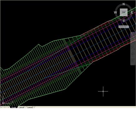
Hello Everyone, I am currently modeling a roadway using a proposed profile and assembly with daylighting cut/fill to an exising surface. The corridor seems to build fine with all feature lines and proper shading indicating areas or cut/fill daylighting but once I create a surface out of the corridor the surface boundarys for the most part will follow the extents of the outer boundary (both by using the corridor extents as outerboundary and using a polyline in the same way) but there are locations where the surface does not build causing the outer boundary of the surface to enter the corridor and follow the edge of pavement instead of where the daylighting meets the ground. the bluish green lines which intersect the corridor lines are the outer boundary of the surface created from the corridor. Anyone have any idea how to fix this? Thanks -mraymer
-

Triangular segmented mesh mountains...
lamensterms posted a topic in AutoCAD 3D Modelling & Rendering
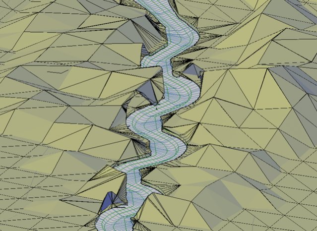
Hey guys, Im doing a little graphic work (moonlighting) and was looking to create a jagged mountain-scape with triangular facets/faces (similiar to this image)... I was just wondering if you guys can please advise me the best method to creating such a mesh/surface/object. Most of my 3D modelling experience is limited to using 3DSOLIDs... and I cant really think of a good way to create this shape. Any help is greatly appreciated. Cheers.
-
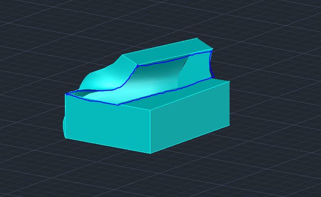
Hi All, Looking for some help with what is probably a fairly basic 3d Modelling operation. I have a series of planar surfaces arranged to create a relatively basic object. I am now trying to use the sculpt command to convert these into a 3d solid but keep getting the error message; "Modeling Operation Error: Operation did not add or remove material. Solid creation failed, no watertight volume detected." Is there any way of; A. forcing the sculpt command to work through altering some sort of fuzz distance option etc? or failing this B. identifying the non compliant sufaces involved so I can attempt to tweak them to suit? Thanks Al
-
I'm trying to rotate this TIN surface, but it won't rotate. I select it, do the ROTATE command, pick the rotation while seeing the how the surface will look, click, and nothing happens. An alignment won't rotate either. The polylines I just made will rotate though. Anyone know what might be going wrong? EDIT: The items that won't rotate are data references. I assume that's why they won't rotate. There must be something extra I need to do to rotate them?
-

[3D]"Transfer" differents surfaces into a single plane
JulioPieri posted a topic in AutoCAD 3D Modelling & Rendering
Hello, I'm making a car model on autocad 3d and I have to make all of its differents surfaces flatten on a same plane (similar to papercrafting). I must get the "real sizes and dimensions" of all rectangles and triangles that compounds my model. This is about 20 differents planes defined by the lines of the car. The idea of this project is to make it possible to build the car from a printed paper. Ive tried to use UCS making the "new xy" plan on the diferents surfaces but it would take like a day to make this in the whole model. I've also tried rotating the surfaces, but inst accurate enough. The car is not yet solid; I just used the normal line commands. I'm plannig to use 3DFACE to create all the surfaces. The only thing I could come up with was to define various UCS and then use 3DALIGN with a previous rectangle made on the WCS. But this is not very efficient. Does anyone have any suggestion? Is there any way to "transfer" the differents surfaces to a same plane so that I can get the "real dimensions" (the real area, line sizes) of them? I'm not sure being clear enough.. Thanks! -
Hello all, I have been scouring the net looking for a way to read in the DXF data for a surface entity in AutoCAD2012. There's plenty on reading in simple objects (e.g. 3DFace, Points, etc.) but nothing on surfaces. The data itself is also not as intuitive as I would have hoped. The DXF reference PDF from AutoDesk shows 7 possible unique entries and the data I need is most likely stored in the proprietary data. So, in short I know where it is but how can I read it? The DXF format is fairly new to me so any help/guidance would be fantastic.
-

How to create surface or solid from contour lines?
mihailklenov posted a topic in AutoCAD 3D Modelling & Rendering
Hello, there! For several days now I've been trying to lay a mesh on top of some contour lines. I've also tried the loft command, but with little success. I've tried several terrain plugins, but they all seem to misfunction because I have overlapping contours. Here is the dwg to get idea what I'm trying to make. I'll be very grateful to all kind of suggestions on how I can do it. (including recomendations for plugins, other software or whatever else) Thank you in advance! contours.dwg -

Applying a Surface/Turning a series of Curves into a Solid Object
gp11g08 posted a topic in AutoCAD 3D Modelling & Rendering
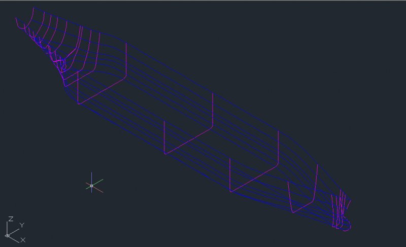
Good Afternoon, I am currently working on a project that involves some basic collision simulation of an LNG ship in Solidworks. However, before I can do that I need to turn the ship (which at the moment exists as a series of curves, see attachment!) into a solid object, which I can then export as an IGES file. So far I have tried the PRESSPULL command on the advice of someone, and it hasnt worked at all, only produced a "not responding message". Can anyone help me apply a surface, or turn the curves into a solid object? Any help would be greatly appreciated by an extremely inexperienced CAD user! Many thanks gp11g08
-
Hello, I'm using Autocad Architecture 2008 and no matter what I seem to do in Materials Definitions, Style Manager, or Display Manager I cannot get the surface hatch to display on slab edges. Any help would be appreciated. Thanks! img, #cubbies-overlay{ -moz-transition-property: margin, box-shadow, z-index; -moz-transition-duration: 0.1s; -webkit-transition-property: margin, box-shadow, z-index; -webkit-transition-duration: 0.1s; } .cubbies-selected{ z-index: 9999; box-shadow: 3px 3px 8px -1px blue !important; cursor: pointer !important; margin: -3px 3px 3px -3px; } .cubbies-selected:active{ box-shadow: 2px 2px 5px -1px darkblue !important; margin: -1px 1px 1px -1px; } #cubbies-overlay{ position: fixed; z-index: 9999; bottom: 30px; left: 30px; box-shadow: 0 2px 3px rgba(0,0,0,0.; border: none; } #cubbies-overlay:hover{ box-shadow: 0 2px 3px rgb(0,0,0); }
-
Hi, Another day, another problem, this time about Section views, can anyone tell me if its possible to get your data from an alignment? to clarify the way i percieve it to work is Civil3D obtains its horzontial position (chainage) from the alignment and then the height from the surface you select. Is it possible to get Civil3D to take the height from the alignment rather than a selected surface??
-
I want to achieve exactly the same thing as shown in this video http://www.youtube.com/watch?v=0hlLIkXxIxk&feature=related I did as instructed and confirmed that I want to transform it to a mesh. But as I proceed and push the Smooth Object button, I receive the following message: ‘A smooth mesh cannot be created from at least one of the selected objects. Smooth meshes can be created only from 3D solids, 3D surfaces, 3D faces, polygon meshes, polyface meshes, regions, and closed polylines.’ Any ideas, which step I ignored?
-

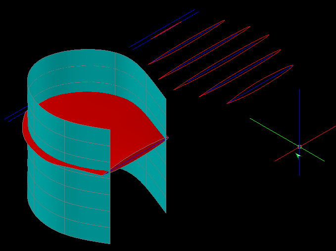
Subtracting Lofted Surface using Extruded Surface - Doesn't Work
dulerong posted a topic in AutoCAD 3D Modelling & Rendering
Hi all, Problem: Green Surface = Extruded Surface Red Surface = Lofted Surface I'm trying to subtract the green surface from the red surface. Commands Tried: - Subtract - Surftrim So far these two didn't work out very well. "Subtract" didn't do anything at all, while "Surftrim" helped me to get rid of anything outside of the cutting surface. But the problem: After Surftrim, the lofted surface's inside shows out, and I found out that it's not solid/filled inside, but rather it's a hollow space inside the lofted surface. I'm trying to create a fan blade, and using that green surface as a shape-maker. Anyone has any idea? P.S. The original post and picture owner is in this link http://www.cadtutor.net/forum/showthread.php?47775-How-to-draw-table-fan-blade
-
I am trying to model a bottle in solidworks. I know how to use boundary, loft, sweep tools. But i don't where to start the model. The height of the bottle 240 and width 85mm and thickness 1mm. Any ideas?
-
Hi, This should (on the face of it, parden the pun) be an easy task. I created a lofted surface over 3 scketched lines. The result is a niceCAD Tutor.zip curved surface. I then thinkened the surface and converted to Sheet metal. At this point I expected to just set the sheet metal defaults to the same 6mm as my thickened surface, and create a flat pattern. But Inventor seems to not find a bend and errors!! So I try Unfold, no joy....Any one got a solution, please? .ipt attached Many thanks, Jon
-
I am just beginning to create TIN models, and was curious how much time people spend actually perusing the triangles for anomalies or mistakes or even how efficient they were created? Mine are not that big, and in a couple of hours i can look at each TIN for efficiency but is that a poor use of time? I am not sure how well to trust the TIN model! TIA, Darren
-
I am working with a line of points based on a surveyed power line. I want to build a surface using the elevations of the points. The kicker is that they are very linear (power poles, after all, are all in a line). I want to copy & offset the points 50 ft on either side of the surveyed points to create an area to create the surface from. As it is right now I get a knife edge surface that is not useful. If there is a better way to approach this, please enlighten me! Thanks
-
Currently, I am trying to make a TIN from predefined contours of both the existing ground as well as the proposed ground so that I can perform volume computations. I am able to create the surface but the problem I am having is getting the units of the contours and the units of the surface to agree. For example, I was given a file from the surveyors that has contour lines with elevations ranging from 175 to 185 feet. When I make a TIN surface from the contours, it converts the elevations of the contours into feet, making my surface elevations range from approx. 14.5 to 15.5 feet and thus throwing off the volume calculations but a factor of 12^3. Can anyone help me get this straigtened out? Is there a setting that I am missing or something to cause this to happen?