Search the Community
Showing results for tags 'alignment'.
-
We often have ditches in roadway cross sections. I create a feature line to model the bottom of the ditch, so that there's a target for the slope into the ditch. My question is, is there any way to specify a point by providing a station and an offset off the road alignment, so that I can place the feature line nodes accurately? What I've been doing is 1) draw a series of circles centered on where the sample lines cross the centerline; 2) draw the feature line with each vertex at the intersection of a circle and a sample line; 3) provide the elevation based on the elevation needed in the cross section. Yes, it would be more efficient to draw one long segment and let AutoCAD extrapolate the elevations, but our ditches never line up that neatly. A better question might be, is there a more efficient way to create a ditch in cross sections? Up until now, we've been doing all this by hand. Judging by the lack of discussion on this particular item, it's so easy nobody has problems, or they're doing it manually too.
-
This is more of a solution than a problem, in case it happens to someone else. tl;dr: When you publish a sheet set, you may get an unexpected alignment in your output. I have a drawing created with LDD. I wanted to add a sewer profile, so I created an alignment. The alignment object was on layer 0 (not my choice), so I hid the object. It didn't show up in print preview. It didn't show up when I printed that one sheet to PDF. When I printed the whole set to PDF, though, the alignment appeared on the plans. I have no idea why the "Dwg to PDF" plotter prints an alignment that doesn't print any other way. To fix it, I created an alignment style that puts everything on a non-plotting layer; problem solved.
-
- sheet set manager
-
(and 1 more)
Tagged with:
-
 Hi all, how is it possible to get and put alignment of a MTEXT object via AutoLISP? I appreciate any help.
 -
Hello, I'm having an issue when I launch the geometry editor for alignments in autocad Civil 3D 2016. The command launches but the geometry editor box never shows up. Things I've tried; audit, purge, super purge, recover, tried pulling the box from offscreen with alt + space, repaired and then reinstalled autocad civil 3d 2016. This problem persists in all drawings I open in 2016. I've looked through forums on multiple sites but can't seem to find anybody who has duplicated this issue. At this point I'm willing to try every suggestion, maybe I missed something simple? Thanks in advance
-
Hello all, Has anyone found a way to add additional 'alignment type' groups? Like the currently available groups/categories: centerline, offset, curb return, etc. Any help is appreciated Thanks, Phil
-
Hello, I am trying to find a simple way to number alignment segments sequentially and numerically. an example would be changing L1, C1, L2, C2 to 1,2,3,4. I also need this information to be applied to a table and be dynamic. Any and all help is appreciated. Regards, Phil
-
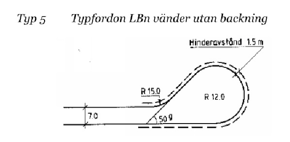
Does anyone has any idea how to model this kind of U-turn which is basically end of the road in the same time and it's curved at the end?
-
Hi there, I've found many instructions for using Civil3D to place alignment station markers, but I was wondering if there is similar functionality in Map3D or a LISP routine that accomplishes something similar?
-
Hello all, I am looking for a way to append a remark/comment column at the far right of my alignment table. The desired result would be to have a character, a simple hyphen, in every 'remark' cell and be able to revise it to be a comment specific to the line/curve in that same row. Any and all suggestions are appreciated. Regards, Phil
-
XPIPE/XTUBE Not Showing Up in Particular File and Feature Lines
darkman257 posted a topic in AutoLISP, Visual LISP & DCL
Hello - New here and new to lisps. One Question: (second question was answered on another thread) I found the xpipe and xtube lisp from another thread and it works but it has stopped working in one particular file. If I open a vanilla drawing, draw a pline, and do xpipe/xtube it works just fine. In the file I am working on however it does not want to work anymore. I have exited and reopened and reloaded the lisps. All I get in 2-d is a circle on one end of the pline. I have done audit and -purge and that still did not work. Any thoughts?- 1 reply
-
- xpipe
- feature line
-
(and 2 more)
Tagged with:
-
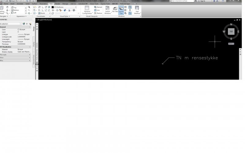
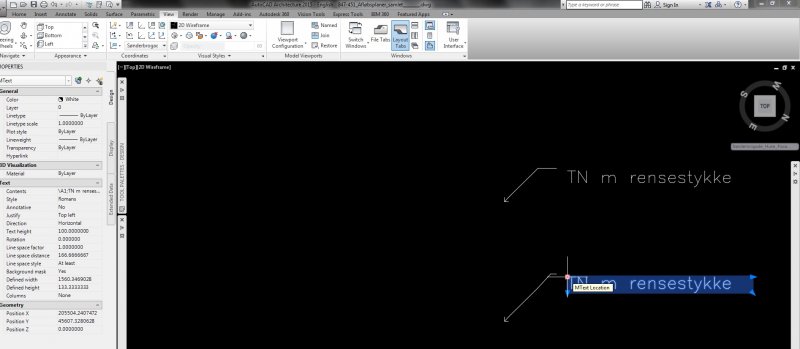
Hi Hope some of you can help solving a problem. When using QLEADER (le enter) in a drawing with custom UCS, the text are displaced away from the leader line. As you can see on attached screen dumps, it looks just fine, when in World UCS. When in a custom UCS, the text are displaced, and when I try to move the text, the leader follows (of course as normally intended). How can I make the text get to place itself normaly, when drawing in a custom UCS (2D) Please help :-)
-
Hello there, I'm using Auto CAD 2013. When i draft on large drawings with a lot of objects sometimes is hard for me to pick/track points automatically. I'm wondering if it's possible to shift between AUTOMATIC and MANUAL point acquisition while drawing without entering options (temporary disable automatic acquisition)? is there a shortcut? Thank you in advance...
-
Hello all, I have received a redesign from a sub that is a bit problematic. I will explain it as best I can. The plan has a main road alignment. I have received a redesigned pipe design. I have the pipe alignment, no problem there. It runs along the road alignment, not parallel, and crosses from one side of the road alignment to the other in several places. The issue is with the pipe profile. The sub created, reused, my road alignment profile and drew their pipe profile on it. They labeled station and elevations on their profile. The stationing is based on the road alignment and elevations are for their pipe profile. Since their profile is drawn on the road profile it is 'stretched' in some areas and greatly foreshortened in others. Does someone know of a slick way for me to project the pipe profile elevations to the pipe alignment so I can generate a feature line? Civil only wants to place the points on the road alignment. I'd just do it manually but it's about 3,500' and a lot of points. Thanks in advance for any help or ideas. Phil Additional info There are only a very few pipe profile elevations that match the pipe alignment geometry points.
-
 I want to make a simple dynamic block showing a plan section of a window with one mullion between the window jambs. I've succeded making the block stretchable to any given length that is required. The problem is, that I can't figure out how to keep the mullion right in the middle between the jambs. Is there any simple way to get there using the actions and parameters in the block authoring palettes? Please help. Thanks
- 4 replies
-
- midpoint
- dynamic block
-
(and 2 more)
Tagged with:
-
We have a user that has an issue where LDD (2009) objects won’t unlock/close. For instance, if she opens a surface, it shows that its locked by her…but if she right clicks & closes it in Terrain Model Explorer, it still shows that it’s locked by her. Alignments are funky too. If she sets one to be current, it should typically unlock the last alignment…but it doesn’t & leaves behind a .lk# file. If I try the same process with the same files on my computer, it releases the locks just fine. She’s gotten pretty good at working around it by deleting the .lk# file from the LDD project folder…but this is obviously a pain.
-
Hello, I am working on an alignment sheet for a gas line. I am showing an aerial in my main viewport in plan view. I am only showing line work between match lines nothing pass that except the aerial. However I have two more viewports aside from the main one. I have one to each of the sides of the main viewport to show the aerial image only pass the match lines. My viewports are locked all three of them, yet my image on the viewports to each of the sides of the match lines keep acting up and won't show correctly every time I zoom out or in. They'll be a time that they will but if I zoom out or in after that they will move and not match my main viewport were the line work is at. I only copied the main viewport and resized it to fit in the template pass the match lines. Created a reference point to zoom into my aerial after the match line and it all works until I'm ready to plot and zoom out then it messes up. Is there a better way to do this? Anyone.....
-
I'm trying to rotate this TIN surface, but it won't rotate. I select it, do the ROTATE command, pick the rotation while seeing the how the surface will look, click, and nothing happens. An alignment won't rotate either. The polylines I just made will rotate though. Anyone know what might be going wrong? EDIT: The items that won't rotate are data references. I assume that's why they won't rotate. There must be something extra I need to do to rotate them?
-

Mleaders text alignment to UCS?
chulse posted a topic in AutoCAD 2D Drafting, Object Properties & Interface
I have an old project where the mleaders were all created in WCS and aligned to it for a preliminary plan set. Now that the plan has progressed to CDs (over a year later) they have rotated the views to a new alignment for the final plans. I'd love to not have to re-do all my mleaders in the new UCS to match the new alignment. Has anyone found a way to update existing mleaders to follow a new UCS? Any help greatly appreciated. Thanks -
Hi All - I am new to Civil 3D and I have just taken over a road job. I had to change the alignment of part of the road section, which I succeed in doing. However, now that I have changed the center line of the road all the cross sections from the change forward are missing. When I look at my alignment gird view all the sections are there and when I click on the line it goes from beginning to end. Any ideas on how to convince the software to print cross sections from beginning to end. Thanks!
-
This is not so much an issue as an addition to the knowledge base here. If someone has had this issue before, I couldn't find it. An associate here was trying to add a couple of PIs to an alignment. When he pulled up the geometry editor toolbar, most of the buttons were greyed out and none of them worked. Part of the troubleshooting SOP is restarting AutoCAD, during which he got a message about enabling macros. The first time he had answered No. This time he said Yes, and the geometry editor worked. So be warned. There are some commands in Civil 3D that depend on macros.


