Search the Community
Showing results for tags 'autocad'.
-
Basically, I want to select two objects, and have them displaced the same amount in opposite directions from a set point without having to do the offset command in the case that the distance may be an odd or unknown value. To summarize, I have two polylines and want to offset them away from eachother using either a typed in distance or a "point-to-point" distance like the current offset command.
-
I have a line that crosses through multiple polygons. Is there a LISP to give me a count of how many polygons this line goes through?

-
Hello Please I need help with my very very old lsp program. It has been made with my colleague in around 1998-1999. Now after a long time we need to edit it to add new block tags and make it count block we specify. We have been working on it almost a week but we really dont have a clue how to edit program after that time. I am asking for a help from some good programmer to help us solve this. All help is appreciated. Lisp file content: (defun f1 () (setq pocs 1) (pp) (if (/= aaa "") (f1a) (setq pocs 0))) (defun f1a () (setq pol (assoc aaa sez)) (if (= pol nil) (f1a2) (f1a1))) (defun f1a1 () (setq cis (cdr pol)) (setq cis (+ pocs cis)) (setq pom (cons aaa cis)) (setq sez (subst pom pol sez))) (defun f1a2 () (setq sez (cons (cons aaa pocs) sez)) (setq nav nil)) (defun f2 () (setq poc (length sez)) (if (> poc 0) (fl)) (while (> poc 0) (setq prv (nth (- poc 1) sez)) (setq zna (car prv)) (setq ccc (cdr prv)) (setq spc (- 16 (strlen zna))) (setq zna (strcat zna (substr " " 1 spc) (itoa ccc))) (write-line zna s2) (write-line zna) (setq poc (- poc 1)))) (defun f3 () (setq pocs 0) (pp) (if (/= aaa "") (f3a))) (defun f3a () (setq pocs 1 pozn (strlen aaa)) (if (= pozn 1) (f1a) (f3b))) (defun f3b () (setq pzn (substr aaa 1 1)) (if (and (>= pzn "0") (<= pzn "9")) (f4a) (f6)) (f1a)) (defun f4a () (fc) (setq pzn (substr aaa 1 1)) (if (>= pzn "A") (setq pocs ccc) (f5))) (defun f5 () (setq aaa (substr aaa 2) pzn (substr aaa 1 1)) (if (>= pzn "A") (setq aaa pzn) (f6))) (defun f6 () (fd) (setq pzn (substr aaa 1 1)) (if (and (>= pzn "0") (<= pzn "9")) (f7) (setq aaa pzn))) (defun f7 () (fc) (setq aaa (substr aaa 1 1) pocs ccc)) (defun fd () (setq pzn "x") (while (and (/= pzn "(") (> pzn "")) (setq pzn (substr aaa 1 1)) (setq aaa (substr aaa 2)))) (defun fc () (setq zn "0" bbb "") (while (and (>= zn "0") (<= zn "9")) (setq bbb (strcat bbb (substr aaa 1 1))) (setq aaa (substr aaa 2)) (setq zn (substr aaa 1 1))) (setq ccc (atoi bbb))) (defun fl () (write-line nadpis) (write-line nadpis s2)) (defun fp () (setq inp (open vyso "r")) (setq out (open "lpt1" "w")) (setq q (read-line inp)) (while (/= q nil) (write-line q out) (setq q (read-line inp))) (write-line " " out) (close inp) (close out)) (defun pp () (setq n 0 zn nil) (while (/= zn " ") (setq n (+ 1 n)) (setq zn (substr aaa n 1))) (setq pzn (- n 1)) (setq aaa (substr aaa 1 pzn))) (defun f8 () (setq nadpis "***** Svitidla dle symbolu *****") (setq sez sez6) (f2)) (defun c:vypis () (textscr) (command "attext" "s" "c:/blok/vypis/material" "c:/blok/vypis/pracovni") (setq pre (getvar "dwgprefix") nam (getvar "dwgname")) (setq n (strlen nam) nn 0) (while (> n 1) (setq zn (substr nam n 1)) (if (= zn "\\") (setq nn n n 2)) (setq n (- n 1))) (setq nam (substr nam (+ nn 1))) (setq zxc (strcat pre nam ".PRN")) (princ (strcat "\nJmeno vysledneho souboru <" zxc ">\n")) (setq vyso (getstring)) (if (= vyso "") (setq vyso zxc)) (write-line " ") (setq sez1 () sez2 () sez3 () sez4 () sez5 () sez9 () sez6 () c3 0 c6 0) (setq sou (open "c:/blok/vypis/pracovni.txt" "r")) (setq rad (read-line sou)) (while (/= rad nil) (setq sez sez1) (setq aaa (substr rad 1 15)) (f1) (setq sez1 sez sez sez2) (setq aaa (substr rad 16 15)) (f1) (setq sez2 sez sez sez3) (setq aaa (substr rad 31 15)) (f3) (setq c3 (+ c3 pocs)) (setq sez3 sez sez sez4) (setq aaa (substr rad 46 15)) (f1) (setq sez4 sez sez sez5) (setq aaa (substr rad 61 15)) (f1) (setq sez9 sez sez sez9) (setq aaa (substr rad 76 15)) (f1) (setq sez5 sez sez sez6) (setq aaa (substr rad 91 15)) (f1) (setq c6 (+ c6 pocs)) (setq sez6 sez) (setq rad (read-line sou))) (close sou) (setq s2 (open vyso "w")) (setq nadpis (strcat " Vykres: " nam)) (fl) (setq nadpis "--------------Zasuvky-------------") (setq sez sez1) (f2) (setq nadpis "--------------Spinace-------------") (setq sez sez2) (f2) (setq nadpis "--------Svitidla dle popisu-------") (setq sez sez3) (f2) (setq nadpis "--------------Ostatni-------------") (setq sez sez4) (f2) (setq nadpis "--------------Ostatni-------------") (setq sez sez9) (f2) (setq nadpis "----------Ulozeni vedeni----------") (setq sez sez5) (f2) (if (/= c3 c6) (f8)) (setq nadpis "----------------------------------") (fl) (close s2) (write-line "Vytisknout na tiskarne? (A/N)") (setq ano (grread)) (if (or (equal ano '(2 65)) (equal ano '(2 97))) (fp)) (read (chr (car (cdr ano))))) Then lisp have two templates 1.material zas c01500 spin c01500 svi c01500 ost c01500 rost c01500 sve c01500 test c01500 2.pracovni ST Z24V V3 V3S VV5 VV766 TOV66 VV666 VV566 VV166 ZV1 TOV VV7 VV6 V644 VV1 Z144 TO44 V744 V544 V144 V2 V7 Z1 TOS TO V1S V51 V66 V6 V5 V1 VYN KR pc ve p boiler N2 VY V SS1 SN SN1 SS Z2 ZST ZSTA DT VYM Z3 Z1P servo SC os iz HOP zem_svorka STM vz Z1v RauchAlarm Z2p ochranaT3 ochranaT3 ochranaT3 tr nap EP1 EP2 V5144 V6644 SSm klim PKZ ZMn VYMN Zm Stlak STH pc44 258 458 158 436 236 149 128 139 124 224 pasLED LEDp LED LEDm S4 S6 S5 vz44 Tx Rx S12 S13 S21 S22 S31 S32 900 120 150 Vm Scm Scs Scv Skm Sks Skv Nkm Ncm 150 60 90 120 Zvv66 V6S VV6 VV6 VV6 VV6 VV6 VV6 VV6 VV6 VV6 VV6 VV6 VV6 VV1 VV6 VV6 VV6 VV6 VV1 S12 S12 S12 S12 S12 S12 VV6 VV6 ZV1 ZV1 ZV1 ZV1 ZV1 ZV1 ZV1 ZV1 V3S Z1 TO V1S V1 pc p boiler Z2 Z2p VYMN V6S ochranaT3 WSB4 All files in attachment. VYPIS.LSP material.txt pracovni.txt
-
Hi Everyone, We are having 25+ draftsmen in our company and we like to have software to track the time spend on the drawings. We use AutoCAD, Inventor, Solidworks and Revit. I saw many software but nothing is as expected. Does anyone suggest software for that? Also please let me know if there is any free or trial version to test before we buy it. Thanks
-
Hello everyone, I'm in a trouble, im making my thesis plans in autocad 2012 version and i need to rescale my plans from 1:1 to 1:100 and 1:300. Thanks for your respond and help.
-
Hello. I am a student and I need your help. My task is to write a program in AutoLISP that draws parts but I have no idea how to do it. The program in the simplest version which is only possible - I know that for some of you it's a bit of a job, so if it was possible, I would ask for help. I will try to repay somehow . Greetings. Sorry for my English.
-
I want to ask you guys what your process is for checking your completed markups? I check my drawings once or twice to see if I picked up everything but it irritates me that when I send it to the engineer I always miss something tiny or something that wasn't marked up at all and I probably should have spotted it...need tips.
-
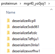
I'm not sure if this is limited to Civil 3D, or whether it applies to AutoCAD also. I'm starting to find that inside of user's %temp% folder, is a subfolder named "proteinrun", and inside this folder are tons of other folders, and inside each one of those, are more files and folders. On the few that I'm run across, there are thousands of files/folders sitting here, anywhere from 6-8 GB in total size. Ultimately, the files, when you finally drill your way to them, are .PNG files. I traced it back to Autodesk because of this KB article - which says it's related to Inventor, and that these files are deleted once Inventor closes. We are not using Inventor, and the files are not being deleted. I suppose it's possible that the files are not being deleted due to application crashing, but I was wondering if anyone else has run across this bloat?
-

Exporting DWG files as readable text files
João Arthur posted a topic in AutoCAD Drawing Management & Output
Hi, I have recently come up with an idea for a project. And to execute that idea i need to be able to read trough a DWG and perform calculations based on the dimensions of walls, windows, doors and stuff like that. Is there anyway i can save a dwg of a floor plan in some kind of text format so i can write a program that is able to read trough it and identify those elements and perform calculations based on those dimensions? Thank You. -
I have an A3 drafting sheet that i want to print out. For some reason i want the print out be be on an A4 paper. Is it okay to print an A3 Sheet on an A4 paper. How will it effect the drawing and the lettering? If not then what is the reason?
-

Toolbars Not Maintaining Specific Properties
ryankevin15 posted a topic in AutoCAD 2D Drafting, Object Properties & Interface
. -
Hello, I'm looking for some help in the task of making my plans less boring. I'd like to use some non - uniform hatches to obtain something similar to the attached image. https://images.adsttc.com/media/images/595d/1743/b22e/38d8/8b00/0036/slideshow/SAN_-_siteplan_-_rooftop.jpg?1499273017 The building probably has a gradient hatch, while the lawn, and the concrete plaza, what hatch did they use for it? Thanks in advance.
-
Hello, I have this very helpful LSP that will add the current annotative scale and delete all other scales for any type of annotative object. Is it possible to modify this LSP so that all objects in the workspace can be selected and this same function can be run instad of doing each object one at a time? CH-ASC.LSP
-

AUTOCAD XREFs ARE ATTACHING XREFS IN THAT DRAWING!
jesterminute posted a topic in AutoCAD Drawing Management & Output
Hi, When I add an xref, let's say floor plans, to my drawing the xref brings in the xrefs in that drawing to my new drawing. I do not want this; nobody wants this. I want to just bring in the floor plans, not the drawings that I attached to the plans. So how do I just bring in just the actual drawing? I hope that makes sense. Hard to explain because there are drawings within drawings. It is driving me insane. -

Help ...move blocks vertically on polyline
mihaibantas posted a topic in AutoLISP, Visual LISP & DCL
Hello everyone, I'm facing a problem ... I have a lot of blocks in the air that need to be connected two by two with a certain polyline. I have a LISP code I've found on the net, I've modified the code, but the blocks do not fall vertically on polyline ... and I can not figure it out by doing the lisp code. I attached the dwg file and the lisp code for example ... I remain deeply grateful for helping:D Example code.dwg MY_snapToObj.lsp -
Hi All, I have an issue about dimension scaling and any tips on how to make them even in paper space so it looks clean and symmetrical for architects to read. There are some drawings i use in MVIEW that are so large that the dimension texts are small. And some that are small that are easily readable. How do i distribute all the dimension font to be even in Paperspace? Any tips are appreciated. Thanks!
-
Hello everyone, I have to draw an adjustable frame (automatic) with a lisp code. The idea is simple (so I think)....I have a fixed point x, y (0, 900) where I need to insert the frame, but the frame must follow my last vertical line of color 8 I've attached a DWG file detailing my requests. I remain deeply grateful for any suggestion of code or income support.... My request.dwg
-
Hello, is there a way to combine the move command with the M2P or FROM command modifiers using LISP? I would want these to be two separate commands. Ideally I would like to program F1 to do _m2p during an active line command and F2 to do from during an active line command... but I'll settle for a lisp that combines each with the move command since I'll be doing that most frequently. Thank you in advance! P.S. here is code that will draw a line starting at M2P.. sort of a start.
-
LSP for changing text inside dynamic block similar to Tcount
ryankevin15 posted a topic in AutoLISP, Visual LISP & DCL
...... -
Mtext Toolbar Button Not Working
ryankevin15 posted a topic in The CUI, Hatches, Linetypes, Scripts & Macros
......... -
Hi need help with a lisp routine to clean up architects drawings with the following. Unlock,Unfreeze & turn on all layers Burst Change all layers to bylayer Change all hatch’s to colour 254 and send to back Change all line weights to 0.18 Change all to Colour 8 Overkill Purge
-

Quickly entering commands tampers with the input
benhubel posted a topic in AutoCAD 2D Drafting, Object Properties & Interface
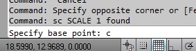
When I enter a command quickly, it will sometimes duplicate my input into the command line. Example: after selecting, if I press "m" for move, and quickly follow it with spacebar to confirm, I will be prompted to enter a base point. Sometimes, it will input an "m" in the command line in the place where I'm supposed to enter the point. I then have to backspace it before I can pick a point. This is happening with other commands too. If I type "line" then follow the last letter quickly with a spacebar (or enter), it will ask me for the line startpoint, with the prompt immediately followed by "e" (which is the most recently input character). It seems to happen more often if I have something already selected, and I have only seen it happen when a command is requesting a point. It isn't reliable, meaning it doesn't happen every time for any command. I thought it was a problem with the keyboard because it recently had liquid spilled on it, but I tried plugging another one in and it also acted exactly the same. It's a new problem that I've never seen before today. I can't get it to happen in any other programs, so I don't think it's my input. It also happens when I open a new drawing. It doesn't happen, however, on any other computers here, only mine. I thought it might be a LISP interaction, but it continued even after disabling all custom routines. Despite being a minor issue, it's slowing me down dramatically. For reference, I've attached an image of what's happening. I didn't enter the "c" in the command line, except previously when entering "sc". Has anybody ever had this happen before, and do you know of a possible cause/solution?
-
Hi friends, this is my first post here . I am relatively new to Autocad MEP . I recently got a job as Mechanical Engineer in an HVAC design and installation firm in a junior level, and I need to practice before joining. I tried learning the software by my own through youtube and several of my doubts have cleared through google. But some things cannot be solved by google search and hence I have arrived here. I have taken the autocad 2d plan of my own house from my Dad , and started practicing drawing and sizing the ducts . I have attached the dwg file here : Final file - https://www.dropbox.com/s/84lqro3b701m6lk/mukatra.dwg?dl=0 Used for Xref ground floor plan- https://www.dropbox.com/s/x8e241aat9pukye/Mukkatra%20mep%20ground.dwg?dl=0 Used for Xref first floor plan- https://www.dropbox.com/s/rqfe5xoyxwhe8r2/Mukkatra%20mep%20first.dwg?dl=0 These are my doubts: 1) I wish to know my duct modelling method is correct or not . I roughly estimated the flowrate required for each room , divided it by the number of diffusers that I wish to place , got the flow rate for each diffuser and assigned it to each diffuser after placing them in a room.I followed this step for all rooms . Then I started the duct drawing . I chose 2 line duct method and started from the major trunk , selected all diffusers of the same floor , got total flow rate and and duct size was obtained (medium pressure lane - velocity around 5m/s). Is this the right method ? 2) I roughly placed the diffusers just to practice drafting. In the professional way, how to place them at particular distance from walls? I know the array function only . May be this question is dump ,but trust me I am new to Autocad thts why. 3) I have assigned different layers for each floor , ie blue for ground floor ducts and red for 1st floor ducts. This was done hoping that I can hide them when needed to take print out . Sorry for my stupid idea , plz tell me which is the real method to take prints in 2d for each floor separately . 4) While taking the 2d view after hiding all other floors , some of my ducts and connectors are partially visible . Its like if some portion got erased with an eraser partially. How to fix this ? 5) This one might be the stupidest of all. Does layer color come in printout ? If I choose light green , Its barely visible ? like that? or all comes in black ? 6) In the schedule table , which I plan to create consisting of duct length and duct size , I wish to give them a series-name or tag . And I need these tags to appear in the drawing on each ducts or very near it. I have no idea how to create tags for ducts. I can only see tags for air terminals and some other stuffs. I need tags for all the things in my drawing. My wish is to make the drawing easy to understand. A simple numbering over the ducts or equipment will be enough . I will sort and group them in scheduling table. 7) Some say , autocad 2d is used for hvac drafting in most companies . Why dont they use Autocad MEP ? The standard library of autocad mep doesnt match with SMACNA standards? Or is it the difficulty to create custom equipment in the library ? Or is it the fact that even if we make in 3d , the printout will be always in 2d ? All the features in autocad 2d can be done in 3d anyway right? Is it possible to change the diameter of an air terminal like diffuser in our list of diffusers ? I know they have different diameters or l x b , but I wish to knw the method for modifying it. When I googled , I saw a big tough method to import a library list or something like this and copy the default list etc etc . I just need to create a new diffuser with a custom diameter with the existing design, possible ? 9) Usually , is schedule table printed along with the plan ? or is it just exported to excel and taken print ? Can the method of scheduling used to create bill of materials in excel ? Is this feature available in autocad 2d? This is a great advantage over autocad 2d? 10) The formula used in duct sizer is the same as the one in autocad mep right? duct sizer uses the simple formula - q= vA and darcy weibash equation right? the same with autocad right? 11) After I drafted , I didnt right click on my duct and choose - 'calculate duct sizes'. Since I had already sized the duct accordingly when drafting by the method described in point -1 . In the analysis tab - view by friction option was there. I was curious and tried it . But the all ducts were green in color despite I saw the duct friction loss higher than 0.7pa/m . Green was supposed to be Out of these questions , I wish to know about the right method to take print (mentioned in doubt 3) for duct plan in each floor separately and doubt 6 is very urgent and consumed my entire day. Please understand that I have been learning this for a week now by my own and many of my questions might be silly for you. The tutorials available in youtube is very less compared to some other software such as solidworks , catia , ansys or abaqus etc . So , each doubt takes a lot of time searching !! Please help guyz , Ill be really grateful . When I become expert in autocad , i will also be helping the new people , but I should master it first
-

AutoCad (Full) 2016 section through RCP
MrButtonmush posted a topic in AutoCAD 2D Drafting, Object Properties & Interface
Hi All, I have a point cloud taken with a Drone and ported to an RCP file via Recap. Whilst I can import and crop the point cloud in AutoCAD easily enough, I simply can't make a section plan through it. I'd really like to be able to do this so I can make site plans. Online videos seem to show you picking a plan or point and getting a "plane" whilst I just get a line. I can pick it but unless I set to boundary it's just a line. If I pick this so called section I don't get the additional option in the section place panel either so !?!?!?! If I upload the RCP would anybody who's well versed in this feature see if they can do it or if the RCP is defective in some way? -
I have a small project on AutoCAD 2016. I was instructed to draw 3D model of Sydney Opera House. Can you suggest me some tips and tricks how to complete it? Espessially it is hard to model the shells. Thanks