Search the Community
Showing results for tags 'move'.
-

Best Method? Move objects in Model space and re-align multiple viewports?
ILoveMadoka posted a topic in AutoCAD 2D Drafting, Object Properties & Interface
I have a a drawing in Model Space and have multiple tabs with multiple viewports all displaying different views, objects and scales of the geometry in Model Space. I now need to move all the geometry in Model Space. I know about ALIGNSPACE where you can adjust the alignment one viewport at a time.. With multiple viewports affected by the model space move, is there a "quick" way to realign all the viewports with their respective geometry? Maybe all at once?? The move will affect them all "relative" one to another. All my searching only returns how to move FROM Model Space TO Paper Space and back Please advise -
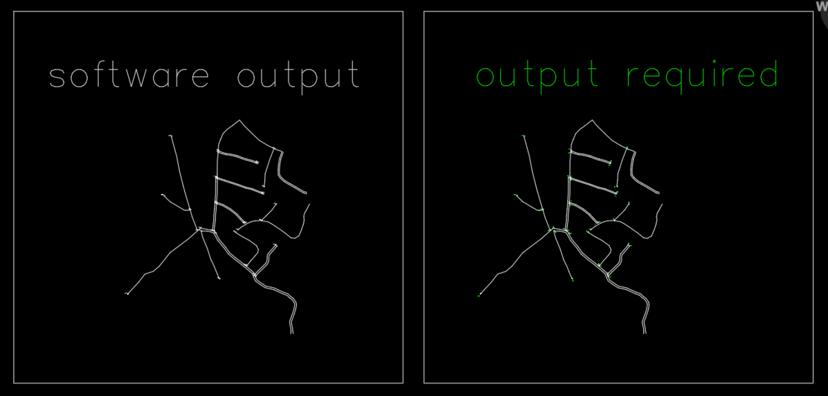
please refer the attached cad file below. on the left is output text given by software at specific x, y distance from center of the circle. i need a lisp routine that will produce results similar to what i have mentioned on right side so that drawing will be easy to read. i have done this manually, but it will take days to complete like this as area is too big. THE TEXT SHOULD NOT OVERLAP TO EACH OTHER AS WELL AS NEARBY POLYLINES. Please help ASAP. Thank You. Drawing1.dwg

-
Hello, is there a way to combine the move command with the M2P or FROM command modifiers using LISP? I would want these to be two separate commands. Ideally I would like to program F1 to do _m2p during an active line command and F2 to do from during an active line command... but I'll settle for a lisp that combines each with the move command since I'll be doing that most frequently. Thank you in advance! P.S. here is code that will draw a line starting at M2P.. sort of a start.
-
I have the code below to place a block on a point. Then array that block based on information given by the user. Then move all of the blocks so that the insertion point is the top and center of all the blocks. It works fine sometimes but about half the time it it skips the first move command. Could someone tell me what I am missing? (DEFUN C:COMEDARRAY ( / OLDL NOR NOC CEB CEP ) (SETQ OLDL (GETVAR "CLAYER")) (COMMAND "_LAYER" "SET" "ELEC-CE" "") (SETQ NOR (GETINT "\nENTER NUMBER OF COMED ROWS: ")) (SETQ NOC (GETINT "\nENTER NUMBER OF COMED COLUMNS: ")) (setq CEP1 (getpoint "\nPICK INSERT POINT FOR BLOCK: ")) (COMMAND "_INSERT" "S:\\LightSett\\LISP FILES\\LISP USED BLOCKS\\COMED PROFILE.DWG" CEP1 "" "" "") (SETQ CEB (ENTLAST)) (COMMAND "_ARRAY" CEB "" "R" NOR NOC 0.6667 0.3333) (SETQ CEP (SSGET '((0 . "INSERT")))) (COMMAND "_MOVE" CEP "" CEP1 (cons (- (CAR CEP1) (/ (* NOC 0.3333) 2)) (CDR CEP1))) (COMMAND "_MOVE" CEP "" CEP1 (LIST (CAR CEP1) (- (CADR CEP1) (* NOR 0.6667)) (CADDR CEP1))) (command "layer" "set" OLDL "") (PRINC) )
-

Move several blocks until they hit in a line or polyline
Elves posted a topic in AutoLISP, Visual LISP & DCL
I need a lisp to move several blocks until they hit in a line or polyline. This line or polyline work like a boundary. Every bloks will end in the same X or Y axis. See result in a attached image. Thanks -

Help - Select lines and overlaping in the same coordinate
teknomatika posted a topic in AutoLISP, Visual LISP & DCL
In the attached file, two lines are represented, apparently overlapping. In fact there is one out of the way between 0.0001. Someone will be able to achieve a routine that makes it possible to select the lines, overlapping them with the same y-coordinate. Of course, also for distant lines with other values. This is an example for horizontal lines but needed equally for vertical lines. Thanks! test_lines.dwg -

problem with displacemet or use first point as displacement in copy, move commands
khoshravan posted a topic in AutoCAD Beginners' Area
I have difficulty on specifying the distance for copy or move commands. It has different options and I have to get my desired result after many try and error. Where can I find a detailed explanation on these commands options? distance, base point and first point as displacement. My exact problem is as follows: I want to move a line 5 cm to the right of present location with orthogonal active . What is the best/fastest way to do this? -
Hello, I'm looking for a macro (preferably. if not, then a lisp) that will allow me to pick an object, then set an imaginary line between two points, and make the object move only along that line. it should be similar to the MOVE command. any ideas?
-
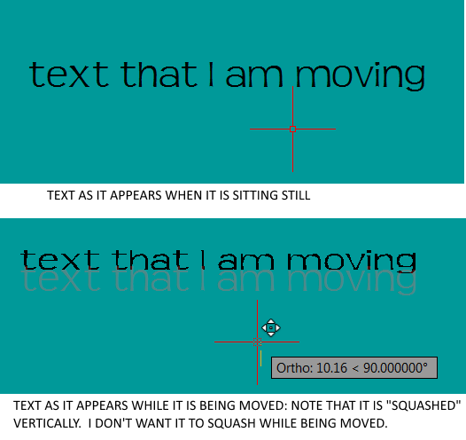
Hi I'm running LT 2017 and have encountered an issue when moving MTEXT. As I move the text, the transparent "placeholder" text is squashing vertically. This makes it hard to know where the end position of the text will actually be. Hopefully the attached image will clarify what I mean.
-

AutoCAD 2011 moving XREF only moves 1/2 or some of the XREF
YPSDude posted a topic in AutoCAD Bugs, Error Messages & Quirks
AutoCAD 2012. Simple nothing else. This has happened to me once before and my manager and I figured it out by accident over a year ago/work around. We don't remember why it happened so here's hopping someone else knows this issue. Basically I have a drawing where I XREF a drawing model in as "Attachment or Overlay" and place it anywhere and some of the XREF'd modeled objects stays at 0,0,0 while the rest is where ever I placed it... If I use the move command like I want to. The objects in the XREF still moves like normal but those objects at the 0,0,0 origin stay. -In the original model I'm XREF'ing in... I deleted a part and put a new part in and saved it.... It still stuck at 0,0,0 -I tried removing and purging but to no help. -XCLIP off don't work. -Saving with the same 2007 AutoCAD formats don't help. -Character Length of file path isn't an issue. -I XREF'd other models in and they are fine. -

Restrict where move parameter in a block can go?
hcostanzo posted a topic in AutoCAD Drawing Management & Output
Is it possible to restrict a move parameter in a block to one of 3 locations? The Cover Sheet Title block we use has 3 options for what a plan set is. The options are listed one below the other with blank ovals to the left of each option, similar to below. o Progress Set o Final Construction o AsBuilt I created a solid hatch, then used a point parameter and move action so that you "fill in" the oval of the correct plan option. The hatch is movable, but it moves anywhere you put your mouse. This works fine, but it would be even better if it could only move from one oval to another instead of all over the place. Any help is greatly appreciated and thanks in advance for any advice. -
I was struggling -first day of self-paced training - with moving holes. This link you posted above was great. That is what I thought Inventor should be capable of. I wasn't finding it. Direct Edit ....assuming this wiil work for solids as well as faces.... ....I'm really green.
-

Need Help With Bounding Box Move LISP! HELP!
tmelancon posted a topic in AutoLISP, Visual LISP & DCL
I currently have a really really basic LISP routine. It was written to center a group of objects within a 12x9 drawing sheet (some people do not care whether their drawing is centered or not... pet peeve) ANYWAYS.. In a nutshell it prompts user to select objects using SSGET. Then asks the user for 2 points, which could be any two opposing points that encompass the outer most limits of the group of objects. After the SSGET and the 2 points have been established I have the routine moving the group based on center of 2 points to the center of the 12x9 drawing sheet. We draw in isometric hence the command snap "I" and "S". I had it snap to Standard so the beginner users can quickly move their cursor to the extents of any given group.. See Code below (DEFUN C:CEN (/ *ERROR* oldsnap oldos) (defun *error* (msg) (if oldos (setvar "osmode" oldos)) (if oldsnap (setvar "snapmode" oldsnap)) (if msg (prompt msg)) (princ) ) (setvar "cmdecho" 0) (setq oldsnap (getvar "snapmode") (setq oldos (getvar "osmode")) (princ "\nSelect Object(s) to CENTER within the titleblock. ") (SETQ CENT3R (SSGET )) (command "snap" "s" "s" "") (setvar "snapmode" 0) (SETQ P1 (GETpoint "\nFirst corner of rectangle: ")) (setvar "osmode" 0) (setq p2 (getCORNER P1 "\nSecond corner of rectangle: ")) (COMMAND "MOVE" CENT3R "" "m2p" p1 p2 "M2P" "0,0" "12,9") (command "snap" "s" "i" "") (setvar "snapmode" oldsnap) (setvar "OSMODE" OLDOS) (SETQ CENT3R NIL) (*ERROR* NIL) (PRINT) ) I would like to use BoundingBox function to Automatically get the coordinates of the SSGET, instead of asking user for First and Second points of rectangle. See Code below that gets bounding box coordinates. Can someone please help me bring these 2 together? Thanks and God bless. (defun c:test ( / OBJ Point1 Point2 ) (vl-load-com) (princ "\nSelect an object: ") (setq OBJ (vlax-ename->vla-object (ssname (ssget) 0))) (if OBJ (progn ;;OBJ is a vla-object ;;Point1 is the lower left point of the bounding box around the object ;;Point2 is the upper right point of the bounding box around the object (vla-getboundingbox OBJ 'Point1 'Point2) ;;Point1 and Point2 are returned as a safearray and need to be converted to a list (setq Point1 (vlax-safearray->list Point1)) (setq Point2 (vlax-safearray->list Point2)) (princ (strcat "\n The lower left corner is " (rtos (car Point1) 2 2) ", " (rtos (cadr Point1) 2 2))) (princ (strcat "\nThe upper right corner is " (rtos (car Point2) 2 2) ", " (rtos (cadr Point2) 2 2))) ) ) (princ) ) -

Dynamic array and move chain wont array
DRBJR45 posted a topic in AutoCAD Drawing Management & Output
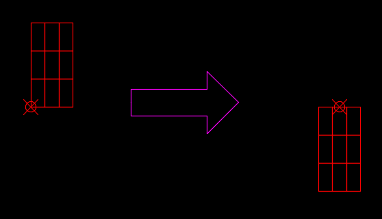
Hello I just can’t get this dynamic block to work. I am trying to chain the array action with the move action and getting nowhere. In the drawing there are 3 objects, blocks if you will. The left block is always stationary, the middle block I want to array, the third block on the right will move with the array to always remain at the end of the finished array. I’ve gone through the process of setting the two parameters to the distance I want the array to be. The first thing I do is assign the array action, pick the middle block (along with the hatch on the left) and then the parameter that will be the action to move the third block. Finally I create the move action and assign it to the third block, save and close. The array works but the block that should move either remains in its position or will move at some odd distance. Any tips on how I should do this correctly? Thanks, DRBJR45 DYN GLASS BLOCK.dwg -

Programming on associative and nonassociative dimensions
Ahankhah posted a topic in AutoLISP, Visual LISP & DCL
Hi CADmates, I have drawings full of dimensions overlapping on each other. Should any one let me know how to get rid of this position via programming? I tried some coding to move text of dimensions, but no success on associative dimensions. ;| (MT:Move:DimensionText<-Ename (car (entsel)) nil 0 1 0) |; (defun MT:Move:DimensionText<-Ename (%ename% %absolute|relative% %x% %y% %z% / *entlist* *assoc11*) (setq *entlist* (entget %ename% '("*"))) (cond ((/= (cdr (assoc 0 *entlist*)) "DIMENSION") nil) (T (setq *assoc11* (cdr (assoc 11 *entlist*))); text position (setq *assoc11* (if %absolute|relative% (list %x% %y% %z%) (list (+ %x% (car *assoc11*)) (+ %y% (cadr *assoc11*)) (+ %z% (caddr *assoc11*))) ) ) (setq *entlist* (subst (cons 11 *assoc11*) (assoc 11 *entlist*) *entlist*)) (entmod *entlist*) ) ) ) I appreciate any help -

Need help with Quick Calculator
Faouweb posted a topic in AutoCAD 2D Drafting, Object Properties & Interface
Hi Is there a way to have in the Quick Calculator the Z axis or X and Y, as shown in the picture bellow. When I need to move something I have to measure, note the dimension on paper, and then use Move , it's not professional Thank you -
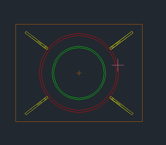
Hi all I have many assemblies modeled, with the drawings done. Now, I got a revision which requires me to change the tube diameter, but I have to "move radially" the reinforcement plates as well. Please see the picture: I have to change a tube dimension from red to green, and I have to "move radially" the yellow plates to touch the green tube. I thought it is a common problem, so AutoCad will have a command. Didn't find it. Ok, there must be a lisp out there. Couldn't find it either. Did I overlook some corner? Is it not too complicate for someone to make one? It certainly is for me. Thanks in advance, NN
-
I have a plane that I created as a midplane between two parallel planes in a part. This part is constrained in an assembly via this plane. I want to move (offset) this existing plane along the x-axis. How do I do this? My reasoning is so that I don't have to reconstrain the part in the various assemblies it is in. I hope this is logical. Thanks.
-
Whenever I use the move command on a line or series of lines that are touching other lines, the lines that aren't part of my selection move with that one line. Here's a series of screenshots showing what I mean. I can't move just that line without moving the other lines around it. Quite frustrating. Anybody know how to fix this? Thanks!
-
How to change the distance between array elements smarter?
khoshravan posted a topic in AutoCAD General
Attached file shows a book cabinet. After manipulating the depth (32 cm) for many times, still I haven't got the ideal depth. Manipulating the distance is time consuming and I am looking for a smarter way to do it. Changing the depth is cumbersome for me, as I act in the traditional way. Let say if I want to change the depth of all shelves to 34, I choose 7 shelves from bottom, move all 2 cm down. In the next step I choose 6 shelves from bottom and move them 2 cm down and repeat until I reach the bottom. In order to draw them, first: I use rectangle not lines which has some shortfalls, second: I use array command to copy them down. This is not a smart way and I think there must be a better way. Although a LISP routine will solve it very easily, but I prefer a non-LISP solution. I would like to know how do you solve this matter? test-change length.dwg -
Hi all and I hope I can put this over properly. Is this possible, as a for instance in Autocad 2011 If I had an heptagan (7 sides) (had to look this up LOL) which was equal sides and I deleted one line, would I be able to move the two end lines together so it is then a Hextegon (6 sides) and they are all still equal??? Or move one of the end lines to close the gap, and all the other lines move with it to keep it in proportion. I have the BIG Autocad Bible but not knowing what the name of this process is, makes it hard for me to look it up. I can select all the lines and move them but not close the gap. Hope this all make sense. Thank you in advance.
-

Move objects apart by a predetermined distance
BrianTFC posted a topic in AutoLISP, Visual LISP & DCL
Good Morning, I was wondering if there is a lisp routine out there that when multiple objects are selected they could be put into a straight line along the X at a predetermined space. I have attached an AutoCAD 2000 dwg to show what i'm looking for. I would appreciate any help. Thanks, Brian MOVE .dwg -
I have saved many useful threads in my subscription folder. They grown and I want to organize them. I have two questions in this regard: 1- It gives 3 folders to build inside subscription folder. Is this the maximum available? Is it possible to increase number of folders? 2- How to move threads I want to categorize them an move some threads to other folders. I couldn't figure out how can I do this. Is it possible? how
-

HELP: Moving DWG's physically & updating an existing SheetSet
shichae posted a topic in AutoCAD Drawing Management & Output
I'm in the process of moving 100+ dwg files physically, but cannot figure out how to update the drawing locations w/o recreating a Pre-Existing fully populated (names, drawing numbers, etc.) SheetSet. Here's what I want to do: Move dwg files from one location to another & update the new physical location (Expected/Found/Relative/Full/UNC Path) in a copy of an existing dst. I've tried moving the files, then updating the Expected Path from within the SSM, but this works on a file to file basis, and takes a long time to perform on a 100+ drawing SheetSet. I've tried using SSMPropEditor, but for some reason, the changes do not stick. The only way that I've found to accomplish this is to use the Archive function (as a folder instead of a ZIP file) from within SSM, but there has to be an easier way to do this... Thanks in advance, and have an excellent day! BTW: I'm using ACAD 2010 on a Core i5 XP machine. -

Selecting objects in a script
Zoe the 3rd posted a topic in The CUI, Hatches, Linetypes, Scripts & Macros
Hello! I'm new to scripting, I dabbled a bit in AutoLisp years ago, but since my new AutoCAD LT doesn't support lisps I haven't retained that knowledge. Anyway... I am trying to write a script that will use the MOVE command and displace an object by a set distance. (I have to do this thousands of times over.) However I do not know how to select the object from with in the script. Anyone know how to do that?