Search the Community
Showing results for tags 'line'.
-
Hello, I am having issues finding the location to set the default table style for a line/curve table. Any help is appreciated! thanks, phil
-
03-26-2016 04:58 PM Hello, I'm doing a project for school and here are the starting directions: "The point of beginning (POB) of this survey is measured from BM#8332. This benchmark is located at the northeast corner of the intersection of SW Washington Street and SW Oleson Road. The coordinates for the benchmark are 1421334.93,783207.62. The first point in the survey for Oleson Village (the POB) is 113.66 feet from the benchmark and at a bearing of N5‹2723W. Note the general location of these points in Figure 2." So here's my issue. I'm trying to draw a line from the benchmark of "1421334.93,783207.62", but the line won't stick to that first point. If I start a line at 1,1, it will stick. If I start a line at 1000,1000, it will stick. Even if I knock off the last digit of each number before the decimal point "142133.93,78320.62", it will stick. Why is this? My limits are set to 2000000,2000000. I'm lost. This is scary becasue I havn't even started the project yet and I've spent 2 hours trying to figure this out. Any help would be much appreciated! Thanks in advance. PS. I attached the project. R, James Final Project.pdf
-
Hi, I was wondering if someone could help me out with the attached lisp file. My company likes to show the storm drain in our base with 4 different lines. One line for the centerline with a global width of zero with linetype continuous that would be on layer A, a polyline for the centerline with a global width of whatever size the pipe is with dashed2 linetype on layer B. The other two lines will offset half the distance of the pipe size from the centerline and will be continuous on layer B. The way the lisp currently works is it Converts selection set of Lines, Polylines, LWPolylines, and Arcs to sets of triple parallel polylines. Outer polylines have zero width and CONTINUOUS line type, while inner polyline uses Dashed2 linetype with user-selected width. I would like it for it does not change the original line i drew but instead copies and changes it to whatever my current layer is and offset it half the size of the pipe to both sides and than changes it to to a polyline with the global width of the pipe size and dashed2. I would appreciate any help. strmpipe.lsp
-
Hi all, was just wondering how to convert a bunch of lines into one continuous polyline?
-

Underlining a single line text
musasiojw posted a topic in AutoCAD 2D Drafting, Object Properties & Interface
How can i underline a single-line text in AutoCAD 2014? -

Can part of line be switched to another layer?
samerickson89 posted a topic in AutoCAD 2D Drafting, Object Properties & Interface
I'm trying to add doors where currently there are just lines for walls. Right now I'm doing that by drawing intersecting lines to use as reference points, using the trim feature to cut where I want the door, then draw the door and delete the reference lines. It's pretty time consuming, so I'm hoping there's a way I can just select two points on the line and switch the layer between those two points, leaving the rest of the wall in the original layer. Does anyone know of a way to do this, or have any other way to make this task go a little faster? Thanks in advance for any helpful replies. -
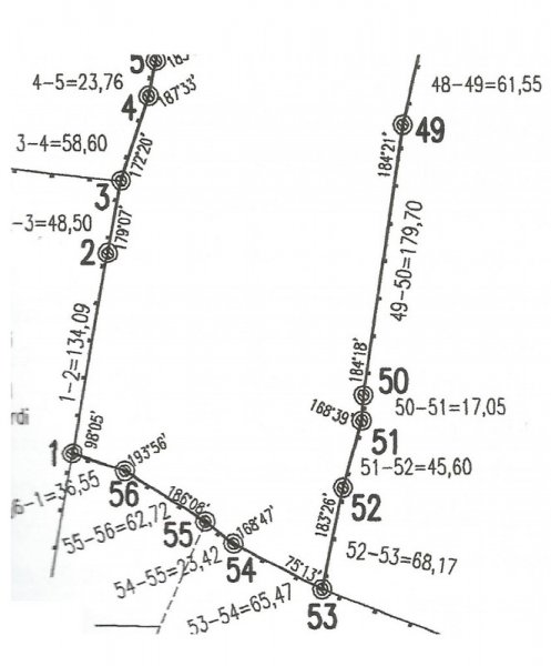
 Hi everybody, I've been reading tutorials about entering surveyor data, but still there is something I don't get it. Let's say I want to draw this scan in autocad (I already know how to enter relative xy/polar coordinates). I guess I should start the polyline at point named 1 and then enter @134.09 Segment 1-2 is visible less than 90º north, but even if I draw a visual aproximation angle for 1-2 to start de drawing, how would I then add the second segment 2-3 with the new bearing respect 1-2? How would I get a true to scan polygone? I will be gratefull of there is any explanation/example. Thanks. Paul
-

A line from point A at a known length to a known plain but unknown angle - HELP :)
macbaydn posted a topic in AutoCAD Beginners' Area
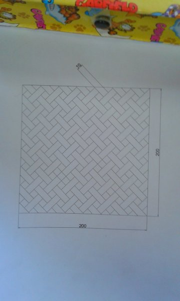
Hi, I want to draw a line on an angle from a known start point at a known length to a known finished plane (but not a known finish point or angle). Hopefully the attached pdf explains it better than I have here. I have turned on OSNAP to get the start point of my line then turned it off again to enable me to select the end point of my line without it snapping to the end or midpoint while it shows the length of my line on screen but this isn't completely accurate. Any ideas would be greatly appreciated? AutoCAD Line Drawing question.pdf -

Very Basic question ! How to break a line into smaller parts?
Atul Kelkar posted a topic in AutoCAD Beginners' Area
I use Autocad 2010 for Arechitectural applications and have a very basic question. Once I have drawn a line & I want to split it into smaller parts, how do I do it? -
I have a drawing with a parcel. I want one of the lines to be straight across with no angle. On the older version of cadd I was able to align a view port to a line. Is there a way to do this with Civil 3D 2015? If so, how would I go about do this? Or does anyone know of a trick they use to achieve this? Any and all reply's is greatly appreciated! Thanks! Miller
-
Hi, i have a little problem with cad... How can i extend line to the surface? Is there any chance to do this? I tried to do this but everything is pointless... Thanks for help e: Ofc line intersects the plane
-

Problem with OSNAP to tangent
Valiance posted a topic in AutoCAD 2D Drafting, Object Properties & Interface
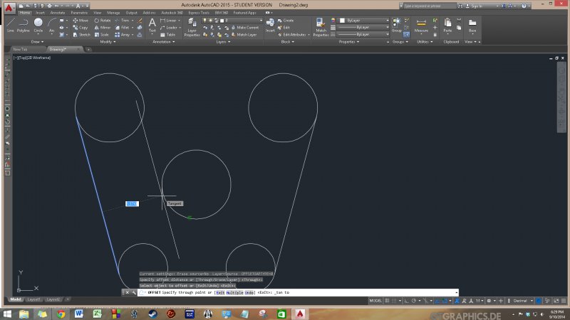
Hi, I'm having a problem with OSNAP and am not sure what I'm doing wrong. As you can see from the attached photo, I am using offset to create a parallel line to the one selected (the leftmost line) that I am trying to place tangent to the circle in the center. However, the tangent snap points (which should be visible in the picture) aren't working properly and cause the line to snap to a position inside the circle rather than tangent to it. My command process is offset -> through -> select line -> select TAN onsnap option -> hover over circle near desired tangent point. Any help would be appreciated. Thanks!
-

Line display not straight - graphic display Issues
kizaerf posted a topic in AutoCAD 2D Drafting, Object Properties & Interface
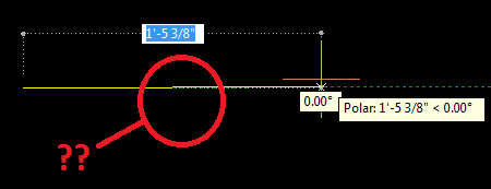
Has anyone ever run into this? As in the image, the line is at 0 degrees and supposedly straight but sure doesn't look it. any reason this may be? Also, sometimes it displays as lines overlapping when there is only one line. This is just in this particular drawing. It's been funky and the cursors are also the wrong color and all these problems occurred at the same time
-
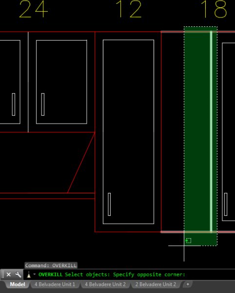
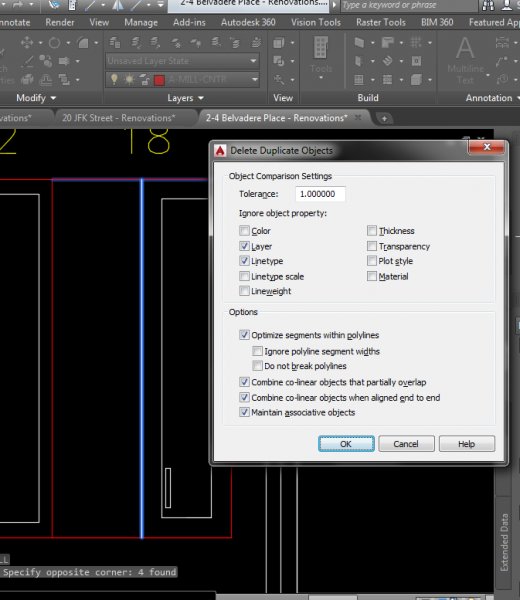
usually it works like a charm but sometimes it plain does nothing. like in this example, there are two overlapping white lines. I do the overkill command and set a high tolerance, but it doesn't do anything. See pictures. why does it work sometimes and then other times it completely does nothing?
-
I need a lisp routine that can take a long polyline and delete all the arc segments, thus leaving multiple shorter polylines (all consisting only of straight segments). Can anyone help me with this please?
-

Lisp to plot multiple lines from a text file of start/end coordinates?
ktd27 posted a topic in AutoLISP, Visual LISP & DCL
We often collect ground penetrating radar data in a somewhat irregular grid of traverses at 90 degrees to each other (loosely east and north) and then put the information on a client's CAD basemap of the site. Our field notes consist of a line position and start and stop position for each line, so that I have a text file arranged as: LINE START STOP 50E 10N 40N 55E 12.5N 40N change direction 0N 50E 55E 5N 55E 50E I'd like to use the text file of these coordinates to automatically plot line segments. Right now, I'm using the line command to specify that my first point is 50,10 and my second point is 50,40...this is fine with small grids, but I just finished a project that consisted of 515 transverses and there must be something more efficient than what I'm doing! I assume it will require a lisp, which I have never attempted to write..any advice? This is my very first forum post, although I've found the community resources to be pretty much a lifesaver in previous projects. I tried a search for similar problems but haven't had much luck beyond finding a routine for auto plotting points. If I've miscategorized, or if this question has already been asked and answered, please let me know! -
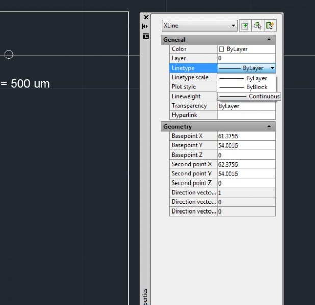
Can someone please tell me how to change a construction line to a "dotted" line? When I draw the construction line using command "XLINE", it is continuous. I had a look at a post but still do not understand it ; reference to http://www.cadtutor.net/forum/showthread.php?11309-Change-a-continuous-line-to-a-dotted-line I know I can change the "LineType" but I can only see continuous line and no dotted lines. Am I missing something? Am I suppose to load something? Please refer to attachment. Thank you in advance.
-
 I'm trying to use a script to draw multiple lines (from one to the next) when I have the quadrants (1-4), bearings and distances in a file...but it doesn't resume the line command from the endpoint of the last drawn line--and therefore "tweeks" (at the * in the short sample script below). line 'bd 5000,1000 3 17.5057 164.71* 2 78.072 31 3 10.111 50 3 19.2147 116 4 66.215 297 Any hints on forcing it to keep drawing, as it does when I hand enter these commands? NOTE: The nice thing I DID learn is that you can bi-pass the [.P .N .G] choices by just putting in the x,y coordinates to start, "tricking" it to thinking you used your mouse. However, the script works for the beginning, but doesn't behave the same as my hand entered commands, but shows the following: Specify first point: 'bd >>Select starting point or [.P/.N/.G]: 5000,1000 Quadrants - NE = 1, SE = 2, SW = 3, NW = 4 >>Specify quadrant (1-4): 3 Current direction unit: degree, Input: DD° MM' SS.SS" (spaced) >>Specify bearing: 17.5057 >> >>Specify distance: 164.71 Resuming LINE command. Specify first point: Specify next point or [undo]: 2 Specify next point or [undo]: 78.072 Zero length line created at (5224.647, 81.665, 0.000) Specify next point or [Close/Undo]: 31 Zero length line created at (5224.647, 81.665, 0.000) Specify next point or [Close/Undo]: Enter BACKSPACE to interrupt script. Command: 3 Unknown command "3". Press F1 for help.
 -

Is there any way to reshape a line to a rectangular?
Sooshiant posted a topic in AutoCAD Beginners' Area
I have hundreds of lines with different lengths and need to change each to a rectangular with the same length and a specified width which I decide. Is there any way to do that for all? -
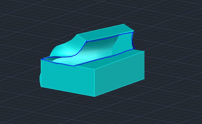
Hello, I've been having a lot of trouble trying to draw the front part of Jose Vasconcelos Library of Mexico Project by Eric Owen Moss. I figured out most of it but I can't close the last space. Any ideas?
-

Linetype "Appearance" in Dialog Box?
tmelancon posted a topic in AutoCAD 2D Drafting, Object Properties & Interface
Never had this problem until now. I just created a new linetype. Basically wanted an even smaller 'hidden' layer. I added it to my .lin file and in my start up lisp routine I have layers and linetypes being added in new drawings, and in old drawings its checking if they exist and if not they are being added. Furthermore, with that being said the new "hidden" layer that I have created is showing up as continuous in the linetype appearance of example of linetype. All I did was copy the current hidden1 and made the new one 50% smaller. See pic for visual of what I am talking about. Any help would be nice. Thanks -
I just want to know the steps how to do this (referred to attached file). I got dizzy :ouch:
-
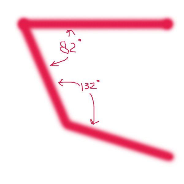
How can I draw the bottom line, with an angle of 132 relative to the middle line? Pulling my hair out here, and I don't have much to spare!
-
I can't figure out how to choose my starting point to be relative to another point without drawing help lines (which mean they must be drawn, selected, deleted = time). I am certain there must be a way around this. For argument's sake, consider I am attempting to draw a cross. I use the line command, input a starting point; choose next point: @100 Now I need a vertical line of equal length to cross the middle-point of the horizontal one. I could snap to middle-point, draw a line of half-length at angle 90 and draw another of 2.(length) at angle -90. This produces 2 lines one of which is unwanted must therefore be selected and deleted. This simple example illustrates my point. I need a command which allows me to choose my first point (for the LINE command) as the point which is "X" units at angle "alpha" relative to a point "x,y" (or a coordinate selected by the SNAP tool if you will). Please take into consideration that the solution must be able to satisfy the stated problem and not the chosen example only. I thank anyone's input in this! Now I gotta put my thinking cap on again...
-
Hello Now that the problem with OS, XP, W7, 16bit, ... is solved with this little lisproutine, which I'm very happy for it, I discover another small limitation. I noticed that it only measures arc's and no lines. Is it possible to fix this problem? It would be great if it also can measures lines (at the same time time) Does anybody can help me with? Thx in advance Gr ARCRLVOOR_DimVoorSnijden.lsp