Search the Community
Showing results for tags 'lines'.
-
Version 1.7.0
4,705 downloads
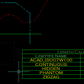
This program will calculate the total length of Lines/Polylines/LWPolylines/Arcs/Ellipses/Circles/Splines with an optional filter. The Filter may be used to select only those lines that are on a certain layer, or perhaps have a certain linetype or colour. The results of the calculation can be displayed in an ACAD Table within the drawing, or written to either a CSV or TXT File. The Table-Style may be selected from the drop-down in the main dialog. Main interface The main dialogue box allows the user to filter lines by layer, linetype or colour and select the table style. Multiple selected items can filtered. A filter string may be entered to help the user quickly find the filter items that he/she requires. Options The options dialogue box allows the user to specify which object types should be included and the type of output, table in the drawing, CSV file or TXT file. Demo Function Syntax: LenCal For instructions on how to run the program see here. Any comments, criticism and suggestions are welcome. Either PM me directly, or reply to the original thread. -

Export 3D lines (and tin surface) to LandXML
B.N. posted a topic in AutoCAD 3D Modelling & Rendering
Hi, I'm modeling for excavations on GPS. The software on the excavators is Trimble Earthworks. I can use file flipper to convert a LandXML file (even a dxf) to a usable format for the machines. My problem: I can export to dxf and only get lines... tin surfaces can't be extracted from a dxf..... I can export to LandXML, but i don't know how to export the lines. The export only seems to use the tin surface.... Anyone has a method? Thanks!!! w0677 0610.dwg w0677 0610-2.dxf -
Hi, I need and thank you in advance for your help. I need to select in a drawing all types of lines except continuous. I tried to use quick select but the tool does not seem to distinguish between this style and the by layer. Thanks!
-

autocad architecture Projecting generated sections to lines
Bojan posted a topic in Architecture & ADT
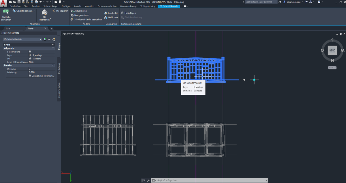
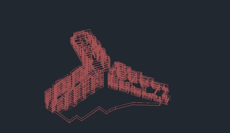
Hello fellow Autocad users, I've recently recieved a messy 3d model (consisting of various geometry types) in order to draw section plans from them. First I tried to generate a floorplan with Autocads "Generate Section/Elevation" tool, thus recieving the projection as intelligent object. In order to draw the plans cleanly from the messy projection I want to transform the projection into a linegrafic, but I can't find a way to edit the projections without crashing Autocad. I also can't use flatshot since the projection is not a Brep. Is there any way to transform the projection into a line grafik, or another alternative to generate cross sections? I've attached an image to depict the problem (I use a german version of AutoCad architecture 2020). Thank you in advance!
-

Help - Select lines and overlaping in the same coordinate
teknomatika posted a topic in AutoLISP, Visual LISP & DCL
In the attached file, two lines are represented, apparently overlapping. In fact there is one out of the way between 0.0001. Someone will be able to achieve a routine that makes it possible to select the lines, overlapping them with the same y-coordinate. Of course, also for distant lines with other values. This is an example for horizontal lines but needed equally for vertical lines. Thanks! test_lines.dwg -

How to calculate monthly advance in polylines/3dpolylines?
toxicsquall posted a topic in AutoLISP, Visual LISP & DCL
Good morning, I have a big problem: I need to make an outline of which was advanced on a road. But I'm doing this activity manually. I tried to use the OVERKILL, but it only deletes the 3dpolylines/polylines that are overlapping and not both. I need only what is different between them and make a REGION or a Closed Polyline of the result. Can you help me? Is there any lisp or a command that can make this? I'm sending the attached file of what I want in order to make an example. Example.dwg -
03-26-2016 04:58 PM Hello, I'm doing a project for school and here are the starting directions: "The point of beginning (POB) of this survey is measured from BM#8332. This benchmark is located at the northeast corner of the intersection of SW Washington Street and SW Oleson Road. The coordinates for the benchmark are 1421334.93,783207.62. The first point in the survey for Oleson Village (the POB) is 113.66 feet from the benchmark and at a bearing of N5‹2723W. Note the general location of these points in Figure 2." So here's my issue. I'm trying to draw a line from the benchmark of "1421334.93,783207.62", but the line won't stick to that first point. If I start a line at 1,1, it will stick. If I start a line at 1000,1000, it will stick. Even if I knock off the last digit of each number before the decimal point "142133.93,78320.62", it will stick. Why is this? My limits are set to 2000000,2000000. I'm lost. This is scary becasue I havn't even started the project yet and I've spent 2 hours trying to figure this out. Any help would be much appreciated! Thanks in advance. PS. I attached the project. R, James Final Project.pdf
-

Aligning multiple lines at once
lucascantelle posted a topic in AutoCAD 2D Drafting, Object Properties & Interface
Hello folks! I would like to know if you guys could help me to align multiple lines to an specific point. Take a look at this image. I want to align all color lines to the white one at the bottom. I tried to move them, but I need a reference point and I do not know how to do it. Ive been searching about it here, but also unsuccessful. -
I want a lisp that when two lines are inserted and they intersect each other at 90 degrees, I want them to create a chamfer
-

TRIM only selected lines
kizaerf posted a topic in AutoCAD 2D Drafting, Object Properties & Interface
So I will select certain lines and do the trim command but it will trim any line that I drag the mouse over whether i selected that line to trim or not. Is there a way for it to JUST trim the lines I select and nothing else? -
I have an issue with my AutoCAD 2010. If I zoom in on a line and select it, the grip for the line stays where it should, but the end of the line move away from it's original location. If I dont have the line selected, I can zoom in to the same distance and closer and the lines do not move. However, as soon as I select it, it moves? As this is a bit difficult to explain, I took a video on my phone and uploaded it to you-tube; LINK: http://www.youtube.com/watch?v=CyYh8Hk04Eg (Apologies for the quality, I lack a video card or video editing software) You can see the line however, every time the line seems to move position, all I have done is scroll in or out using the mouse wheel. At one point you see that I do use the grip to move it, however, the location I move the grip to, is not represented by the position of the line. Anyone had any experience with this issue? And if so, can anyone tell me if or how they solved it? My computer details can be found on the left (it's the home system this issue is reffering to, NOT my work system) Thanks everyone!
-
Hello everyone! Here is my problem, i need to run a simulation model of a building in Fluent Ansys, the thing is i have a model in CAD of the building and i need it to be fully solid so i can convert it to .SAT and import it to the simulation program. I've browsed the forum and the web a bit and the solutions i found didn't work for me. I need a little help. Here's the link for downloading the file, hope it works with links from dropbox: https://www.dropbox.com/s/ncj6knkdslwagv8/Ptam.dxf?dl=0 I tried using the file manager but could only up the pic not the file, maybe is to big... Again the idea here is to try and make this set of lines fully "closed" solid, as the simulation software is "picky" in order to make the meshing for the building. If you need anything else, shoot on. Thanks for the help!
-

Selecting lines/polylines
Loque posted a topic in AutoCAD 2D Drafting, Object Properties & Interface
Good morning all, is there any way (command) that prevents me from selecting lines/polylines/objects, something similar to "imageframe" command. Thanks for the help! -
Is there a way to set a tolerance for trimming lines so minuscule gaps trim?
kizaerf posted a topic in AutoCAD General
The lines are so close that I cannot even see a gap but apparently there is a minuscule gap therefore the lines aren't trimming. Rather than extend all of them, is there a way to adjust the tolerance so they trim anyway? this could save a lot of time. Thanks, K -

How to measure total length of several lines?
Faouweb posted a topic in AutoCAD 2D Drafting, Object Properties & Interface
Hi, I have a lot of lines and I need the Total length, I have them in a separate layer, I have tried with Field and Dataextraction but it is not exactly what I need, or I did not do it exactly. For Field, I can not select all line. Dataextraction takes all lines in the drawing, I need lines that are in the layer. How can I do that? Thank you -
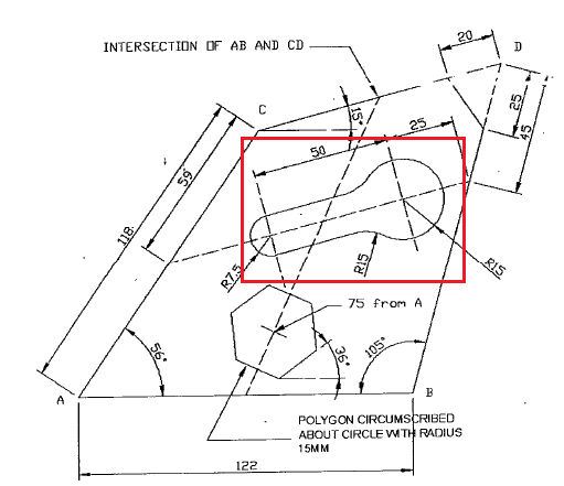
Hello. I need to connect two circles with different radius. Sorry, I don't really know how to explain my question using the right terminology or in the right words. So, here's the snapshot of what I need to draw, the one in the red rectangle.
-
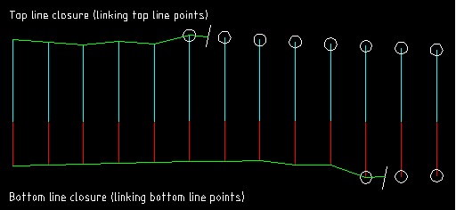
Hello guys, I again, needing a help... Some one knows how do a link with lines as the picture bellow? I have on a drawing lines that need to be closed to make one area, but, to do it it's necessary to get some lines and do a contour line, linking the points... Thanks...
-
Hello there! I'm really new to AutoCAD and I'm basically trying to learn it by drawing simple things. My question is this: how do I change the angle that is between two meeting lines?
-

Lines, Polylines, densify and export
dlm13 posted a topic in The CUI, Hatches, Linetypes, Scripts & Macros
Hi, I cannot for the life of me remember how to get around this one. I have a line with randomly spaced nodes and it also is curved. I need to turn it into a polyline, densify it and export those extra positions. So far I have done line to polyline no problem, but when I try to densify (I have a densify lsp) the 'nodes' are not at the fixed interval where there is a curve. How do I get around this? I have tried exploding the line and joining them into a polyline but it still doesn't work. If I decurve then the curve disappears which is no good as I need the polyline to retain its shape. Any help would be amazing -
Hello folks, Background: During the process of drafting many lines overlap (e.g. construction lines, objects merging, etc) Because the overlapping lines have precisely the same properties, I don't feel the need to remove them. The issue begins when I go to plot. The overlapping lines do appear darker than lines without overlapping. This occurs a great deal in my work! My question is this: Is there a function that will (forgive my Photoshop lingo) merge/flatten these lines so that no more overlapping lines exist? Going in one at a time is tedious business! Thanks, George
-

Lines (angled) move on zoom in but remain static if selected.
afieldoutback posted a topic in AutoCAD 2D Drafting, Object Properties & Interface
I have just been doing some work for a company and they were using AutoCAD 2009. One of my tasks involved stretching and moving items from imported drawings over Architectural layouts. Lines drawn on the x and y axis were fine. However, if I zoomed in on angled lines they moved out of view making them difficult to select or position to a snap point. If I selected those lines then they remained in place when I zoomed in. When I approached the company manager he replied by saying that he would zoom in then zoom out to the point where the lines were correct and in place. I thought that he was either joking or was testing me! It meant I could not do any detailed work - which contradicts the use of Auto CAD. The question has to consider the fact that the lines were angled and that they remained static when selected. When zooming in and selecting them they were off and running out of the screen view. Please also note that my colleague at the next desk opened up the file on V2008 and he could zoom in okay. I was also using a wide screen if this matters. Can anybody help as I am sure someone has come across this problem before? -

Cursor text boxes not displaying...Please help!
SchecterDamien posted a topic in AutoCAD 2D Drafting, Object Properties & Interface
I'm starting a new drawing in Civil 3D 2012 and when I go to draw a line I can't see the small text boxes that show up beside the cursor that allow you to input numbers. I like to type my lengths and angles into these boxes to draw my lines as it makes it 100% accurate however the aren't showing up. Drawing lines is essentially useless because I now have to eyeball it. Is there a keyboard shortcut to get these boxes to display again? Please help. -
So i am confronted with this All my polar tracking options are turned to Zero. (sorry, no pic) strangly enough its does give me one tracking option (read line) wile drawing at 5° and when i draw a square it seems like my plane is off a bit (prolly 5°, looks like a perspective) Tried fiddling around with the DSETTINGS command but nothing goes. so i s my plane off, UCS off, am i a retard Hopefully this is a simple answer , also i get sometimes 1 out of 10 times an innorect SNAP ( snap to a point and its off by a 0,x margin. i Maybe this is connected? I tried google-ing and all but nothing goes. Hope i could get some help here, TNX.
-

Draw a line in profile using stations and elevations
lesalombard posted a topic in AutoLISP, Visual LISP & DCL
I use to have a lisp routine that would draw lines in a profile by typing in the station and the elevation. is this possible anymore. Every lisp routine i find is so complicated, i just want something simple. -

Offestting lines multiple distances in one command?
fisher22 posted a topic in AutoCAD Beginners' Area
Hi, I'm literaly just starting to use CAD so this might be a silly question, but how would I offset a line more than one distance in a command? Is there like a symbol you put between each distance like 2000;2250;2650 or something along those lines (no pun intended). Again sorry is this is a silly question. thanks