Search the Community
Showing results for tags 'autocad'.
-

HOw to Export GPS Coordinates to CSV
wajidgates posted a topic in AutoCAD 2D Drafting, Object Properties & Interface
Dear All, Good Day, I am looking for a method to export all the GPS coordinates which have been assigned to each point along with the properties of that point to an excel csv. In our drawings, there are multiple columns and each column has four points and each point has X,Y,Z coordinates. I want to export all this information to an excel sheet. Any idea? Thank You -
Hey guys, I don't know what I did, but one of my toolbars moved somehow? see below for what I'm talking about. How do I get the above toolbar back down? I've tried clicking and dragging it... I don't know how I got it down. Any help is appreciated

-

Integration of cad dwf files in webpages
ritchie200 posted a topic in AutoCAD Drawing Management & Output
Hi All, I need to integrate dwf files in my web page, please suggest me the Autodesk software(it can be paid software also). There is one more requirement it should fulfill, suppose i want to search for a room in building which has some number or name , i want it be searched in the drawing directly using a query string from the aspx page. Please suggest me if it is possible , if it is please guide me on this. Thanks Ritchie -
Hi guys, I work with AutoCad MEP 2014 not so long. I try figure out how connect my schematic blocks legend with AutoCAD MEP library. Is somebody here who is drawing schematics in MEP? Tomorrow If is necessary i Will deliver some screens
-
If using a Partial customization file that is still in the process of being updated regularly or you’d like that option to updated it, is the best practice to load it via the acad.lsp and your loader through the acad.lsp?
-
Good afternoon. I haven't used autocad since 2002. I am look for a good instructional video that will get me up to speed with regards to autocad 2014. I just downloaded the trial version of Autocad 2014 and I want to become proficient enough to be employable within the next few weeks. I have used Autocad, Catia and Unigraphics in the past when I was in college, but that was years ago. I am looking to get back into the CAD market and find a cad job while sprucing up my skills. If you guys could direct me to an online source that I can view Autocad videos that would put me on a running start, I would greatly appreciate it. Any suggestions would me most appreciated. Thanks in advance autocad 2014, employment, money, cad, autocad, hiring
-
Dear AutoCAD users: We would like to develop a plugin for AutoCAD to create geometries (line/arc/circle/ellipse/polyline etc.) through touchscreen. So instead of using commands, it will be just like freehand drawing, the program will automatically generate shapes to match your touchscreen input. We want to do a little survey here to see if it makes sense to you? Will you buy it? One concern is, because touchscreen input is not as precise as through keyboard & mouse, the dimensions might be a little off (e.g. you want to draw a line with a length of 10.5, the program thinks it is a 10), and you will need to make some adjustments afterwards to get the exact size you really want. Would this be problem for you? Thanks! Disclaimer: We are a startup working on our own project and have no relations to Autodesk.
-
Loading of Bently AutoPlant is well, Piping is also, but when i try to open dialog Component References, AutoPlant shows next message in command: Loading the AutoPLANT Component Preferences. Please wait... Initializing accont (AC_CONTAN18)... Error loading surrogate process windows manager. ERROR: OleManager was not found. What is OleManager? How can i solve this problem? Google is silent! =(
-
Good Day looking for assistance with extracting data from an AutoCAD table. Hav found a fex examples on how to create a table in AutoCAD with VB.Net but no luck on how to loop through the rows and columns in an AutoCAD table and see the items within. Want to be able to loop through a list of drawings, open drawings find the table in Paper or Model space, loop through the records and export them to excel - SQL or XML, or even a simple method of creating a collection if records in VB.Net, where one colud then export the list Any assistnace most welcome Regards
-
I am looking to draw a large lake that I live on that has 14,000+ islands. I have started drawing small sections by bringing in high quality maps and tracing them using the spline command. Is there a faster way to trace the entire lake. I want it to be all drawn with closed poly lines so that I am able to laser cut it and apply hatching. Other tracing programs in which I insert a image of the lake and it gives me the CAD format are very inaccurate and a pain to work with. What do you recommend? I have attached a small section of what I am trying to trace, I want the islands to be traced.
-
Hello, I'm starting out with Autocad and I have a little question that may sound a little dumb to you'll but is really troubling me. I'm using autocad 2004 and when I try to draw a line in feet, the line just goes out of the the screen and the screen just doesn't scroll. It works fine when it is around 1 or 2 feet, but just goes out of the page when i try to draw above 5 feet. Please help me with this.
-

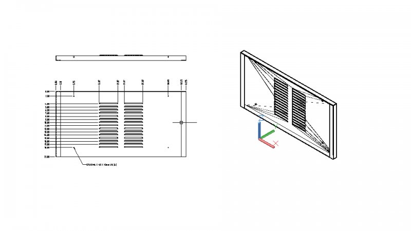
What is the name for this type of partial slot for air passing ??
zmarcoz posted a topic in AutoCAD Beginners' Area
I want to check whether any official name, size, etc for this type of air slot. Thanks
-
I have few .arx applications for AutoCAD. In these applications few are menu based and others are command line. Now what I am trying to do is, Load the .arx app, run it and then unload it once the .arx application runs through a LISP command. .arx applications run once the user clicks on the tabs that are provided. .arx applications are written in VC++. Now I have a lisp file, which gets loaded once the user starts AutoCAD. In the lisp files I have declared these functions for various .arx applications; (defun c:XYZ_program() (command) (command) (arxload "C:/ABC/XYZ.arx") (command "XYZ_program") (arxunload "XYZ.arx") ) It works fine for Programs which need input data from Menu based forms, but says error unloading xyz.arx for programs which need command line input. I was wondering if there were any commands in LISP that will make sure arxunload "XYZ.arx" will execute only once (command "XYZ_program") is executed. I am not sure on how to approach this problem. Any help with the same would be greatly appreciated. I have also discussed this question with others in the following link, but did not find much of help. http://stackoverflow.com/questions/17602443/loading-and-unloading-the-arx-file-with-lisp You can have a look at it, just to gather some information, in which direction were we heading.
-

migration toolbars from ACAD 21007 to ACAD 2014
alninek posted a topic in The CUI, Hatches, Linetypes, Scripts & Macros
Hi, i'm italiann i'm sorry for my bad english: i'll try to explain my question better i can i wish to migrate all default icons of AutoCAD2007 to AutoCAD2014: i' ll wish to overwrrite default icons of 2014 with icons 2007 is it possible?> i know that i can do this with cui save every icon in a bmp file and sustitute every icon of 2014 with bmp file of 2007.... but i think it s so boring to do... does it exist any faster mode? thanks in advance for answers P.S. i tried to export in a cui file all default toolbar of 2007: ii opened it in 2014... but icons are 2014 default!!!! same file cui opened in 2007 and 2014 has different icons images!!!!!!!!!!!!!!!!!!! -
Apologies in advance if this isn't in the most appropriate category. I recently started work at a marketing firm that was seeking people experienced in Revit. I used it a lot in school so I thought, awesome. When they told me more about the position, they told me I'd be using the software to create furniture pieces that'll go into rendered floorplans and their goal is for the pieces to look as real as possible in the rendering. Creating pieces wasn't something I did a lot of in my classes but I thought a challenge would be welcome. The problem is that I have one coworker who did very basic training in the software and that's it. No one else knows anything about Revit so I figured this is a good place to ask. I've found that tables are easy. Anything with edges, I'm fine with. But when pieces are supposed to have softer edges (like pillows, beds, chairs, etc) I'm having more trouble with making them. I've tried using the Model In Place option and the start from scratch option where I just go right into making a new component. It's a bit time consuming, but I'm hoping it's just because I'm new at it. I've even used the 3D Modeling part of AutoCAD 2013. It does make cushions easier but there's still some things I'm just not able to figure out. My main question is this: is it possible to make detailed/realistic furniture pieces for Revit (like things I would find on RevitCity) in Revit itself or should I use other AutoCAD software. The other two I've been looking at were Inventor or 3DS Max. I used Inventor a bit in classes for designing mechanical pieces and loved it. I've never used 3DS but I checked into it on YouTube and the videos show plenty of things I could use at work. Any helpful opinions on the matter would be greatly appreciated. I don't mind if I end up having to learn another program, as long as it makes things smoother and quicker in the long run.
-
Is there a way to create a lips program or a vba macro to offset a line on both sides, keep the source, then trim all the content between the two offset lines and delete them. Or is there a way to create the same effect around a MLeader? Something like the described on the attached imaged
-
Im trying to plot a 3D object in Autocad 2009 but can't remove the hidden lines. The "Hide" command removes the appropriate lines in the viewport and in the print preview but the print-out still appears with all the lines.
-
Hi, How can I draw a 3d arrow in autocad 2012? (where the arrow head is a cone, or something that appears in all view angles). Assuming the answer will be a cone and line grouped, how can I rotate them (I seem to be able to rotate only in the xy plane)
-
Hi, the problem I was facing (and still facing) was that I use my mouse middle button (scroll) as pan when clicked, But it poped out menu for snap overrides, then I resolved this issue by MBUTTONPAN variable by setting its value to 1. Now when I start a new file or a new session it reverts back to snap override menu and I have to again use variable. The changes I am making are not lasting more then a drawing. Can any one tell me what's causing this and how can I resolve this. Once I made a change in variable it should be permanent unit I change it again, but it is not. So does any one have any solutions. I have also tried profile for this case, but same results. Even the changes I have made to FILL or TASKBAR or ZOOMFACTOR and many like this which I am used to are not working more then a drawing. Would appreciate any one's expertise.
-

subtract command not working like expected after import
jcc5018 posted a topic in AutoCAD 3D Modelling & Rendering
Hey guys, I am working on a project where I am attempting to design a pendant. I wanted to do this in solidworks but I am not as experience with that and I'm having issues, so I went to what I know, AutoCAD. Unfortunately I am still having problems and I think it has to do with the import file from Adobe illustrator. What I have is a circle with different parts and block text that I would like to cut out. I saved the illustrator file to a dwg file and it imported with a hatch over all the solid areas. I deleted that to get the respective outlines, and extruded. Most loops extruded but some failed to do so for some reason. But I have an option to convert to a pline, but then I get a specify precision dialog which adds a bunch of points along what seems to be a straight line. Anyway, when I do manage to get things extruded, and go to perform the subtract command (or intersect which would be faster) I click the main shape, and then click the items I would like to remove, but it doesnt do anything. I have no idea what the problem is. Does anyone have experience with this? I did get one whole to subtract, but I really dont know the difference between that and the others that made it work. (P.S. If anyone has experience with solid works, I imagine this would be the same process. But I can get the outlines to appear, and extrude the outside shape, but I can't figure out how to get the inner holes to cut out.) Unashamed2.dwg -

is there a way to plot multiple pages from one layout
ittayd posted a topic in AutoCAD Drawing Management & Output
I have a model with many items, each needs to be plotted from several views. One option is to create a layout per view, which means a lot of layouts to manage. Is there another way? Where I can create a layout with several views so that plotting it will create multiple pages? -
Hi there, I Posted This problem twice but it doesn't showed in the forum. I don't know why, whatever, My problem is making Array with a circle and a line[same as to radius]. When i use array between them to create 9 more lines, some lines are becomes bigger then the original line. why this happen? I attach a file to be understand clearly. Zoom the intersection point of lines and the circle. Any suggestion will be appreciate . Thanks in advance, Provas.
-

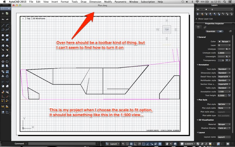
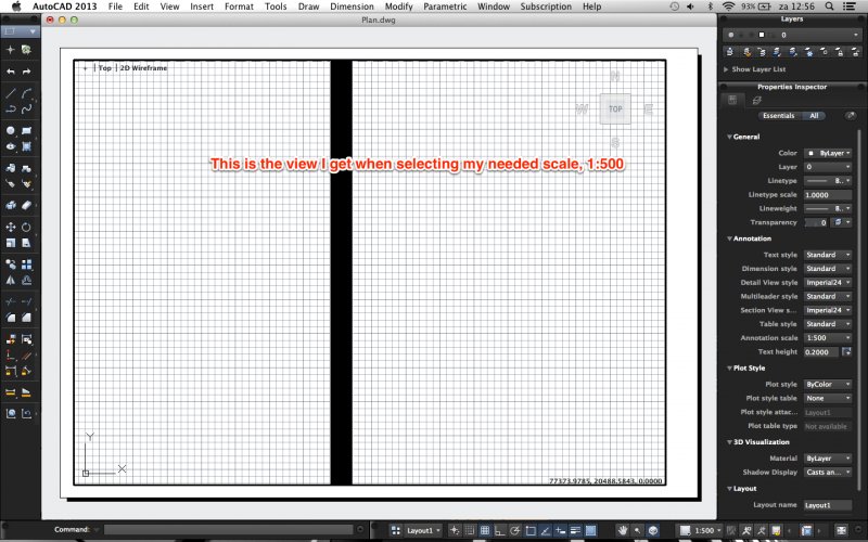
Lay-out doesn't scale right
progvincent posted a topic in AutoCAD 2D Drafting, Object Properties & Interface
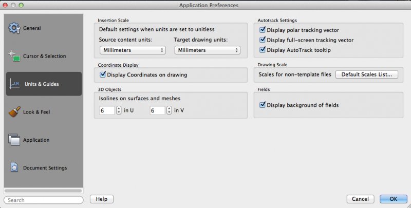
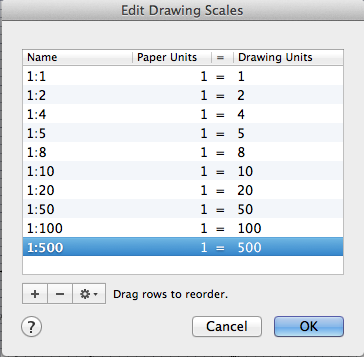
Hi, I've got a drawing of a site, which is about 144 meter long, so 144000 mm to put it in autocad units. I drew it completely in millimeters, and made a new scale in the layout view 1:500, all my units are set to millimeters. I would expect when chosing the scale 1:500 it would precisely fit on my paper, as 144000/500=288 and the longest side of an A4 paper is 297. But somehow, when chosing the scale, things get seriously messed up... My drawing is no longer recognizable at all as it is zoomed in way to far... Any ID's what I'm doing wrong? Also, when watching youtube video's about lay-out, I always see a little toolbar under the main frame (the one where your title stands) saying things like new viewport and page setup. Somehow it's not visible with me... How can I turn it on? In attachment you can find my autocad file and some screenshots about my problem. Thanks in advance! Vincent Plan.dwg
-
Hopefully I can explain this well enough, I've been pounding my head on this for weeks. I have created an autonumbering lisp routine for block attributes that has a start value, increment, insertion order-forward or reverse, so I can autonumber blocks with a specific scheme. I work with wiring and electrical systems. My problem now is I have new blocks I've created for devices that need to be autonumbered, but they need to have a scheme like X3-1, where X3 is an alias and -1 is a wire location. I can have #1-24 on the wire location, then the next block needs to start at X4-1 and go through 24 again. How can I add a loop and range to my lisp to accomplish this or does someone have another idea? We work with hundreds of devices so it is not practical to number by hand like I have been. Any input would be appreciated. Thanks
-
Good day, dear Forumers, just recently our company partially switched from AutoCAD to Inventor, my department however still works with AutoCAD. This however means that I am required to edit "2D" sketches made with inventor. After struggling a bit with converting the new format into something I can actually select, I've come across a new problem: once I dissolve the block which contains the main model I am unable to convert the resulting lines into Polylines. only 50% of the lines actually connect to their adjacent lines/arcs. This means I have to redraw half the model, which, as you may agree, is unacceptable. Quite lenghthy web-searches have not been fruitfull. FLATTEN was suggested but I don't have the expess tools installed and don't think I can convince the admin to do so. Also it seems that All lines/arcs in question already are on the same Z level, namely 0. Thanks in Advance, CP++