Search the Community
Showing results for tags 'scale'.
-

Dynamic Block with different x,y,z scale?
Jmclachlan posted a topic in AutoCAD 2D Drafting, Object Properties & Interface
As a result of multiple updates of AutoCAD software and addition of 12D software I have lost the ability to block replace a block with different x,y,z scales with a dynamic block and have the dynamic block retain its function. Is there a way for the dynamic block to work with different x,y,z scales? -

Link Dynamic Scalebar to Viewport Upon Insert
bretwieseler posted a topic in AutoCAD 2D Drafting, Object Properties & Interface
Hello, I don't even know where to begin... I'm trying to construct a scale bar that can be linked with a chosen viewport, upon insertion into paperspace. Civil3d 2015 already has several of these "preloaded" in the Layout Element panel, but these scalebars are not "smart", requiring input from the user (I'm trying to create these for newbies in our office). Any thoughts or help is appreciated. -
Hi all, Ok, so I am a newbie here (and to AutoCAD). I did attend a beginners 4-day course a few months ago (before I got CAD in work) and I've forgotten half of it. I started on a new template - changed 'units' to architectural as this project needs to be measured in feet & inches. I started a general floor plan (mainly by using straight lines to mark out rooms etc.) All fairly simply. Then I came to putting in doors and went straight to 'blocks' only to find that there obviously wasn't any there. Through the help of online tutorials, I've drafted a new block called 'door' designed it (straight line & arc etc.) and edited the block to apply 'stretch' and 'flip' commands. All ok. I set up a new layer called 'Doors' (just in case I want to hide them at some point) and set it as 'current'. When I inserted a block of the door - the scale of it is totally wrong? I went back in to block editor and the door is set up properly. The properties say all measurements are correct, but the inserted door is tiny. (I can obviously adjust it on screen to look right, but when I use the measure tool to check - what should be a 3'6" door it only measures 1'10" - even though it looks right?) I've tried block editor a million times - and tool palettes too, but I can't figure out why the door is not inserting into the drawing to scale? Please help - I'm hitting my head off a brick wall here... Thanks in advance.
-
Hello, I have made some object addon on a large outdoor festival plan made years ago. When I mesure some object I add, the mesure shown are'nt good. If a make a new object with the same dimension and I move it over the old one, the scale is match. I to fix those different scaling? Thank you.
-

Problem with macro for creating several dimension styles
Sandervp posted a topic in The CUI, Hatches, Linetypes, Scripts & Macros
Hello everybody, I've created a macro for creating different dimension styles for different scales. We are using these dimension styles in our company. It works well if I use it in a new, empty drawing. But if I use it in an excisting drawing with a dimension style with the same name, I have got a problem..... I'll see this in the command line; "Enter name for new dimension style or [?]: "scale 20" That name is already in use, redefine it? :_dimclrd Invalid option keyword. That name is already in use, redefine it? :" "_dimclrd" should be the next command in the macro, but because "scale 20" is already in use, I need to do some other commands first. AutoCad stops with this macro at this point. If the first dimension style, which the macro should be create, already in use, the other dimension styles shall not be create. Is there a possibility/ sollution to change my macro so he creates every dimension style what he supposed to do? Also if one or more dimension styles already excist? The reason why; if you delete a dimension style because you think; "I don't need him any more." But you're wrong. Or somebody else goes further with the drawing and needs to draw something with another scale. You need to copy the 'wanted' dimension style from another (new/ excisting) drawing. Could somebody help me? This is the whole macro; ^C^C_dimclrd;1;dimltype;continuous;_dimlwd;-1;_dimdle;1.25;_dimdli;1.25;_dimclre;1;_dimltex1;continuous;_dimltex2;continuous;_dimlwe;-1;_dimexe;1.25;_dimexo;1.25;_dimblk;"";_dimldrblk;"";_dimasz;2;_dimcen;0;-style;;iso.shx;a;;;0;;;;;no;_dimtxsty;standard;_Dimclrt;2;_dimtfill;1;_dimtxt;1.8;_dimtad;1;_dimgap;1;_dimtoh;off;_dimtih;off;_dimtmove;0;_dimscale;1;_dimdec;0;_dimzin;0;_dimtolj;0;_dimse1;off;_dimse2;off;_dimrnd;5;_dimtofl;on;-dimstyle;s;"scale 1";_dimclrd;1;dimltype;continuous;_dimlwd;-1;_dimdle;1.25;_dimdli;1.25;_dimclre;1;_dimltex1;continuous;_dimltex2;continuous;_dimlwe;-1;_dimexe;1.25;_dimexo;1.25;_dimblk;"";_dimldrblk;"";_dimasz;2;_dimcen;0;-style;;iso.shx;a;;;0;;;;;no;_dimtxsty;standard;_Dimclrt;2;_dimtfill;1;_dimtxt;1.8;_dimtad;1;_dimgap;1;_dimtoh;off;_dimtih;off;_dimtmove;0;_dimscale;2;_dimdec;0;_dimzin;0;_dimtolj;0;_dimse1;off;_dimse2;off;_dimrnd;5;_dimtofl;on;-dimstyle;s;"scale 2";_dimclrd;1;dimltype;continuous;_dimlwd;-1;_dimdle;1.25;_dimdli;1.25;_dimclre;1;_dimltex1;continuous;_dimltex2;continuous;_dimlwe;-1;_dimexe;1.25;_dimexo;1.25;_dimblk;"";_dimldrblk;"";_dimasz;2;_dimcen;0;-style;;iso.shx;a;;;0;;;;;no;_dimtxsty;standard;_Dimclrt;2;_dimtfill;1;_dimtxt;1.8;_dimtad;1;_dimgap;1;_dimtoh;off;_dimtih;off;_dimtmove;0;_dimscale;10;_dimdec;0;_dimzin;0;_dimtolj;0;_dimse1;off;_dimse2;off;_dimrnd;5;_dimtofl;on;-dimstyle;s;"scale 10";_dimclrd;1;dimltype;continuous;_dimlwd;-1;_dimdle;1.25;_dimdli;1.25;_dimclre;1;_dimltex1;continuous;_dimltex2;continuous;_dimlwe;-1;_dimexe;1.25;_dimexo;1.25;_dimblk;"";_dimldrblk;"";_dimasz;2;_dimcen;0;-style;;iso.shx;a;;;0;;;;;no;_dimtxsty;standard;_Dimclrt;2;_dimtfill;1;_dimtxt;1.8;_dimtad;1;_dimgap;1;_dimtoh;off;_dimtih;off;_dimtmove;0;_dimscale;20;_dimdec;0;_dimzin;0;_dimtolj;0;_dimse1;off;_dimse2;off;_dimrnd;5;_dimtofl;on;-dimstyle;s;"scale 20";_dimclrd;1;dimltype;continuous;_dimlwd;-1;_dimdle;1.25;_dimdli;1.25;_dimclre;1;_dimltex1;continuous;_dimltex2;continuous;_dimlwe;-1;_dimexe;1.25;_dimexo;1.25;_dimblk;"";_dimldrblk;"";_dimasz;2;_dimcen;0;-style;;iso.shx;a;;;0;;;;;no;_dimtxsty;standard;_Dimclrt;2;_dimtfill;1;_dimtxt;1.8;_dimtad;1;_dimgap;1;_dimtoh;off;_dimtih;off;_dimtmove;0;_dimscale;50;_dimdec;0;_dimzin;0;_dimtolj;0;_dimse1;off;_dimse2;off;_dimrnd;5;_dimtofl;on;-dimstyle;s;"scale 50";_dimclrd;1;dimltype;continuous;_dimlwd;-1;_dimdle;1.25;_dimdli;1.25;_dimclre;1;_dimltex1;continuous;_dimltex2;continuous;_dimlwe;-1;_dimexe;1.25;_dimexo;1.25;_dimblk;"";_dimldrblk;"";_dimasz;2;_dimcen;0;-style;;iso.shx;a;;;0;;;;;no;_dimtxsty;standard;_Dimclrt;2;_dimtfill;1;_dimtxt;1.8;_dimtad;1;_dimgap;1;_dimtoh;off;_dimtih;off;_dimtmove;0;_dimscale;100;_dimdec;0;_dimzin;0;_dimtolj;0;_dimse1;off;_dimse2;off;_dimrnd;5;_dimtofl;on;-dimstyle;s;"scale 100"; Thanks -
Hi There, Could do with some help/advice on this matter: I've completed a set of drawings - floor plans and elevations - with ACA. Now I'm creating sheets and I setup the pages in A3 size. Most of my views, when drag and dropped from the project bar onto the A3 sheets fit nicely except one. This is the Site Plan which longer than the others since it includes the surrounding landscape. My initial solution was to change the sheet size to A2. But is there a way to scale the drawing to fit the A3 page? Should I go to the construct and use the scale tool? I'm thinking select all, scale it down by 50% so the scale changes to 1:100 to 1:200. What if I want to scale it to 1:150, then I scale it down by 66.666%? That doesn't sound quite right. I know for this particular project I can just change the sheet to A2, but for future reference and of course for my own knowledge I'd like to know what the best options are... thanks a bunch!!
-

How to print a drawing with draftsight at a specific scale?
sinergy posted a topic in AutoCAD Drawing Management & Output
Hi what steps need to be followed to print a drawing at a specified scale? Like 1:100 or 1:200 etc? I guess the starting point is that the original drawing is at full size scale or 1:1. How do I know that? Thanks -

Losing the Linetype from XREFS
the_arkitek posted a topic in AutoCAD 2D Drafting, Object Properties & Interface
Hello, We xref and draw in Model Space then use viewports with title blocks scaled accordingly to the LTSCALE in Paper Space (i.e. 1"=50'-0" would have a setting of LTSCALE: 600). So this happens frequently....We receive a background from architect, civil engineer, etc.. and after cleaning up the background and then setting up our drawings, thus xref in the background; the linetypes from the xref get lost (i.e. say a dashed line will show continuous). Any help would be greatly appreciated!! -

How to create various scale output of a given image file
coralflame posted a topic in AutoCAD Drawing Management & Output
Hi! I have a 1:50000 jpeg image of a sample map and I wanted to create output images of 1:25000, 1:12500, 1:10000 and 1:5000. How can I do that without sacrificing the quality of the original file? Thank you in advance. -
 Hello, I know this is a user error on my part, Bu I cannot figure this out for the life of me. My company have a set of blocks in a .dwg file on its own - let's say they are circles with radii that vary by 10'. In another drawing I want to divide a polyline using a one of these circle blocks at a specified number of segments. My process is to copy that block from its original file into my new file with the polyline - now I am able to list the block when I go through the divide command. MY ISSUE is when I complete the command, my block, as it is distributed along the polyline, is 1/12th the scale of the actual block I copied into my drawing. (it's something with the 12 inches are in a foot deal). It's like the divide command scaled it down...I can't explain why though. Both of my block units (the original file block and the one produced by the divide command in my new drawing) are set to inches and both drawing files are set to arch. - inches. The weird thing is that when I copy the block over into my new drawing it is at the correct scale. It is just this block - when brought in through the divide command - is scaled by 1/12. Thanks in advance,
 -

Help! Can't convert drawing from mm to inches!!
alexstephens7 posted a topic in AutoCAD 2D Drafting, Object Properties & Interface
I am trying to convert a drawing from mm to inches which should be totally simple. Everytime I scale it in the drawing it becomes completely unreadable and looks insane. When I block the entire drawing and try to insert it into a new drawing set in inches it is huge and I cant pan or see anything except the corner of the lowest wall and the program starts acting glitchy. I'm not sure if the way the original drawing was set up could have something to do with this? I'm working in autocad 15 for mac. Any help would be really appreciated! -
Hello, I've drawn two autocad drawings. Everything is in meters and has the right distance (1meter in autocad is 1meter in real life.) The drawing is 2d. Now I need to make a PDF from this drawing. I need to do this by deleting all the layouts and after that right click at the layout and click at plot. I just dont see how I need to take the right scale. Whenever I use as plot area Window and press fit to paper it looks good, but if I enter a scale, the only outcome is 1:1 which is kinda weird because my drawing is about 10 meters long and I need to plot it to A3... How the heck can I make a good plot by chosing a scale that actually works and I can draw in my drawing? Thanks in advance, Chris.
-

Determine what a viewport's custom scale is
blowther posted a topic in AutoCAD 2D Drafting, Object Properties & Interface
Hi all, Does anyone know of a way to determine what the custom scale of a viewport is? I have some existing drawings that are using non-standard scales and simply state 'Custom' in their properties window. -
I am currently attempting to draw shop drawing of a frame storefront in autocad, the problem I am running into is the frame is 10' tall, when I put the 10' into the line command in the model window it exceeds the window and I can not view the line. Everything I have read says to build my drawing 1:1 first before setting it to the 1/2"= 1' scale specified for the shop drawings. Anyone sure where I should start to resolve this issue?
-
Can someone please confirm my sanity? I seem to remember in the not so distant past that Autocad had a system variable that stored the last scale factor used by the scale command. The command line would display something like this: Specify scale factor (Copy/Reference) : The previous scale factor being shown inside the "" (1.0000 being the default). You could just hit enter and it would automatically scale the new selection set by that scale factor. This feature still works, if you just hit enter without specifying a scale factor, you will get the previous one. However, it is no longer displayed in "" and I can't find anything referencing a variable that is storing the last scale factor. Btw, I'm using Autocad 2013
-
Hey guys, It has been years since I have touched AutoCAD and I am creating a small drawing for work, i have a question about view ports in layouts looking into models. So basically, if i have a drawing of a car, id want a viewport in my paperspace layout to focus on a wheel. how can i get a paperspace viewport to center on the wheel from my model space? I have tried changing the geometry options in the viewports properties, but that focuses on its position in the paperspace layout?
-
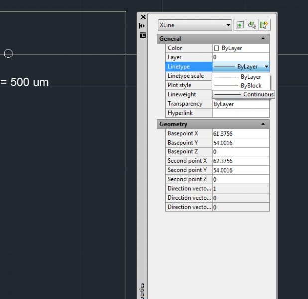
Can someone please tell me how to change a construction line to a "dotted" line? When I draw the construction line using command "XLINE", it is continuous. I had a look at a post but still do not understand it ; reference to http://www.cadtutor.net/forum/showthread.php?11309-Change-a-continuous-line-to-a-dotted-line I know I can change the "LineType" but I can only see continuous line and no dotted lines. Am I missing something? Am I suppose to load something? Please refer to attachment. Thank you in advance.

-
I've been trying to plot a drawing from the layout, I made a viewport and scaled it 1:25. however when I preview the print (I'm printing to pdf by the way) the lineweight is out of scale and I've checked the option "scale lineweight". Even if I uncheck it, the lineweight stays the same
-

Print CAD Drawing according to desire scale?
tipu_sultane posted a topic in AutoCAD Drawing Management & Output
I just want to print a CAD drawing according to some required scale. Please help me I have never done this before. I needs some hint. 1:1 1:2 1:3 1:4 1:5 1:10 1:100 Another thing what if I convert the drawing having specific scale into PDF format and print it. Are the scale remain same? If I scaled the diagram say in A4 paper then print this on A3 paper the scale remain the same? -

Linetype scales, model vs paper space
bobsy852 posted a topic in AutoCAD 2D Drafting, Object Properties & Interface
I've had a problem with linetype scales for some time now and I can't seem to work it out, so I'm finally getting around to asking on here.... When I draw say a dashed line in the model space it sometimes looks broken exactly how I would expect it to look. Yet when I then set the drawing up in a viewport within the paper space it looks like a continuous line. It also plots as a continuous line. The only way I have found of working around this is to change the linetype scale of the line in question (usually to around 0.012) this then usually gets the line to display dashed as expected on the paper space. It is very trial and error though with different lines requiring different scales? I wondered if there is a setting so that they display in the model space exactly as they would display in the paper space or vice versa? Thanks for the help. Rob -

PLEASE help with hatch edit!
ColinPearson posted a topic in AutoCAD 2D Drafting, Object Properties & Interface
Hi all - I don't know what happened, but I was CADDing along and now when I double click a hatch, it invokes what I think is the Quick Properties, not the Hatch Edit command. I can still type the Alias "he" and get to it, but I'm used to double clicking and don't see what change. I looked in the CUI, and under Double Click Actions>Hatch, the Hatch Edit command is listed. What gives? THANKS to the community at large, as always. -
Hi, I've created a drawing in model space in centimeters which I originally drew on A4 paper @ 1:100. When I bring it up in paper space I have to make it 1:10 to fit. Do I need to scale the drawing in model space using z enter s enter 1/10 xp enter to make it the correct scale? I find the scaling issues very confusing! The site itself is fairly large, 15m x 3.5m
-
Hi there, i am facing problem to make change the elevation in Autocad'07. I tried "ELEV" command to done this. Elevation changes when i'm changing it but when i drawing a object i found all the in 0 elevation. whats the solution? And Another question is , Is it possible to scale up a particular object without changing its dimension? such as i draw a beam and its section,, i want the section Larger(without changing its dimension) but the beam as it is. Any answer will appreciated. Thanks in advance.
-
I'm a beginner using AutoCAD 2014. I am still confused when it comes to My units and plotting to scale. If I want my drawing at 1/8" scale what would I set my units to and what would I set my scale to when plotting? Any information at all would be helpful.
-
Hello, well i have a problem on solving an autoCAD homework . i have a pdf with the contours of the altitude of an area and i have to rasterize it as an image in AutoCAD 2006 (i put it on windows paint , then i save it as an img (jpg) ) and then i inserted it in AutoCAD. I have to georeference that image and to fix its scale. How can i do that ? Drawing2.dwg